I did another batch of Furuta pendulums and took a timelapse of the assembly:
These were done in a bit of a hurry, and nothing was changed from last time. At some point I'll probably do a refresh of the design, though. After building 16 of these, I have a bunch of ideas about things I'd like to do differently, and I've gotten a few feature requests from the recipient as well.
I built 6 furuta pendulums for a university controls class:
Since the original furuta pendulum was all built out of scrap I had lying around, I had to redesign pretty much everything from scratch.
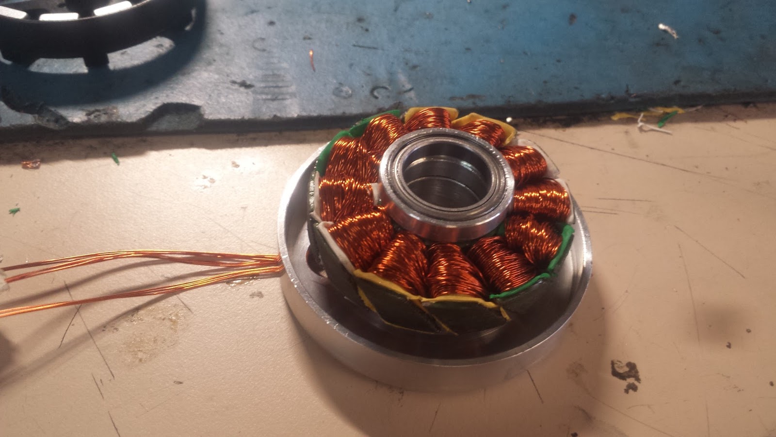
Instead of using a hand-skewed motor like the original, I used a custom-wind of a T-motor gimbal motor. These have low enough cogging torque to work pretty well:
Each motor gets a Microfit connector crimped on the leads, and a hollow shaft retaining-compounded in, for the encoder wheel to attach to:
The spindle has a pair of bearings very lightly preloaded by a wavy washer, and a diametrically magnetized magnet in the back which is read by a hall encoder:
In the base is a US digital 20k count/rev optical encoder which the wires for the pendulum hall encoder pass through:
SPI to the pendulum encoder gets passed over a 12-pin slip ring, with each pin doubled-up for (hopefully) better reliability:
In the base there's a board with power switch, mode switch, DC input jack, USB connector for serial communication, and programming header on it. The mode switch allows the pendulum control to be done by the on-board motor controller, or by taking commands and passing back sensor outputs over serial to a computer running the controller.
I didn't want any screws to show, so the top is held on by 4 magnets:
With the mechanical bits out of the way, it's time to go through the process of controlling the inverted pendulum. Brace yourself for babble about transfer functions and other controls stuff. Video at the end.
First on the agenda is getting the brushless motor to actually produce torque. While I'd already done 99% of the work required, I still had to redo the current d/q axis current loops.
After some decoupling the motors d and q axes look like independent RL circuits, and are thus easily tamed with PI controllers. Since the control loops are running on a microcontroller, it makes sense to design them directly in discrete time, rather than in continuous time (although designing in continuous time, assuming you sample fast enough for it to not make a difference, and converting to discrete time can be valid too). To do so, first find the zero-order hold equivalent of the RL circuit - basically, how the dynamics of the circuit appear to the microcontroller sampling at a fixed rate.
Remembering good ol' 2.004, the transfer function of a series RL circuit from voltage to current is $$\frac{I(s)}{V(s)} = \frac{1}{(Ls + R)}$$ which has a frequency response like this:
Now let's convert that to discrete time. Some amount of algebra (or numerically in one line of Matlab using c2d) later, you get:
$$\frac{I(z)}{V(z)}=\frac{\frac{1}{R}\Big(1-e^{\frac{-R\dot{}Ts}{L}}\Big)}{z -e^{\frac{-R\dot{}Ts}{L}}}$$
Where R and L are the same resistance and inductance as before, and Ts is the sample period. The frequency response looks a lot like the continuous time version, except that the phase (and magnitude, but to a lesser extent) gets kind of wacky towards π radians/sample.
Okay, now to design a discrete current loop. I like to write a PI controller in the form
$$\frac{U(z)}{E(z)}=k\Big(1 + \frac{ki}{z-1}\Big)$$
which has a pole at z=1, a zero at z=1-ki, and a high-frequency gain of k. This way, changing k only changes the loop gain, and changing ki only changes the zero location, unlike the typical parallel PI expression.
Set if we set the zero of the controller on top of the pole of the RL system, then the controller * RL just looks like an integrator. This can be done by setting $$ ki = 1-e^{\frac{-R\dot{}Ts}{L}}$$
Now just to choose a loop gain that achieves whatever crossover frequency (ωc) you want. Let's say something like π/8 radians/sample, to be conservative, because, to quote a professor, "There are always higher-order poles". This should be reasonably conservative and give us ~78 degrees of phase margin, as you can tell from the pole-zero map of the return ratio (in this case the circuit times the controller, which is just an integrator):
From the same geometry, you can see that crossing over at ωc = π/2 gives you 45 degrees of phase margin, etc.
We can calculate approximately the loop gain required by doing some more geometry on the bode plot of the return ratio. We want the loop to cross over (magnitude = 1, or 0 dB if you prefer dB for some reason) at π/8 radians/sample. We also know that, at the frequency of the controller zero and circuit pole, the plot has a magnitude of k/R. Since the slope of the magnitude plot is -1 (on a log/log scale), we can easily calculate the k required to join those two points with a line of the correct slope:
So k should be ...
$$k=r\Bigg(\frac{\omega_{c}}{1-e^{\frac{-R\dot{}Ts}{L}}}\Bigg)$$
This won't be quite exact, because the slope of the magnitude plot isn't perfectly -1 between those two points, but it gets you pretty darn close.
Here's some MATLAB plots verifying the frequency and step response of the current controller designed this way.
Hey, I just worked that all out symbolically.... that means that if my motor controllers could measure resistance and inductance on their own, they could auto-tune their current loops....(also note this isn't specific to current control of RL circuits. It can just as easily apply to any 1st-order kind of system, like velocity control of a motor (inertia -> inductance, damping -> resistance), etc)
With torque (well, current, but close enough) control out of the way, next step is stabilizing the pendulum upright. While there's always the "I heard PID controllers were good so lets throw PID at it and plug in arbitrary constants until it works" strategy, which people on the internet seem to like, that's not very interesting. There are lots of reasonable approaches, but the one I've mostly been playing with is full state feedback with LQR-chosen gains. While I've taken a class on state space modeling and controls, I had never actually implemented such a controller in hardware, on a microcontroller.
Like most good controls problems, the first step is coming up with a model of the system to design the controller around. For the near-upright position, the furuta pendulum system can be greatly simplified from the extremely unpleasant full equations of motion. Rather than doing the proper thing and linearizing those about the pendulum-up position, I was lazy and converted my rotary inverted pendulum into a cart-pole, and linearized those equations about vertical. Except that has been done for me dozens of times.
The quantities that need to be converted to go from the rotary inverted pendulum to cart-pole:
The only trick is that care needs to be taken doing this conversion- both going from physical device to the model, and from controller gains back to the physical device when implementing the controller. In the model, the units are meters, kilograms, and Newtons, whereas on the device they are radians, kilogram-meters^2, and Newton-meters respectively. This model is only valid for small rotations on both axes, but it seems to be good enough to stabilize the system well.
The upright-controller, for reference states of zero, looks like this: $$ \tau = 0\dot{}\theta - 0.1\dot{}\dot{\theta} + 2.52\dot{}\phi + 0.15\dot{}\dot{\phi} $$ where tau is torque, theta is the angle of the base, and phi is the angle of the pendulum (from upright)
Something to note: I put no weight on the location of the pendulum (i.e. the x-position of the cart in the cart-pole system), so the gain in front of theta is zero. This was mostly an aesthetic choice - I thought it would look nice if the pendulum slowly coasted to a stop after being disturbed.
Positions are taken straight from the sensors. Base velocity (theta dot) is measured with this trick, and pendulum velocity is the (heavily filtered) derivative of angle, since I can't time edges on the Allegro A1335 position sensor used for pendulum angle.
Here's the disturbance response (i.e. me flicking the pendulum) of pendulum angle with two different controllers, as compared to the model used to come up with the controller gains.
To actually get the pendulum to the upright position, I (roughly) used an energy-shaping controller. Check out the 6.832 notes here for a more detailed description of how that works. The basic idea is to apply a torque to the pendulum only when it adds energy to the pendulum, and only do so while the pendulum has less than its upright energy) In other words, the sign of the torque applied to the pendulum should be the same as the sign of the angular velocity of the pendulum, so that torque times angular velocity (i.e. power) is positive. By doing the opposite, you can remove energy from the system, if you want to swing down from upright, for example. At the end of the day, my energy shaping controller looks like:
$$\tau{} = K\dot{}cos^4(\theta{})\dot{}\dot{\theta{}}\dot{}(9.81(1-cos(\theta{}) )-.0075\dot{\theta{}}^2)$$
Tau is torque, theta is the pendulum angle. K is a constant found through experimentation. The 9.81-.... term at the end is proportional to the additional energy needed to bring the pendulum upright. The 4th power cosine term has the effect of skewing the controller output towards the bottom of the swing, when the pendulum velocity is the greatest. This term was actually sort of an accident. By some miracle, the swing-up controller worked the first time I implemented it, without that term. But when I later went to write a linear swing-down controller, I realized that, at the bottom of the pendulum's swing, my angle measurement was rolling over. The angle jump of 2 pi caused a spike in velocity which gave a "kick" to the energy-shaping controller. Once I fixed that problem, the gain of the controller was too low to do anything, so I cranked up the gain. I found this new controller to not be very effective, and would mostly cause the motor to spin around a bunch. So I added the 4th power cosine term to add back the "kick" back to the bottom and that fixed it.
Here's what the angle and torque command during swing up look like, before it kicks into the linear controller. This is actual measured data:
Finally, there's a simple state machine which chooses the controller to use at any given time - swing up, swing down, or stabilize up.
Here's a video showing the different control states:
This is a relatively quick little project, but one that's been on my mind for more than a year now, and finally got around to building.
Inverted pendulums can be a pretty cool testbed for controls stuff. They're relatively simple, but very non-linear systems, and there are a lot of approaches to swinging up and stabilizing the pendulum. The Furuta pendulum style of machine is particularly interesting, I think. If built right, they can be very small but have unlimited travel, unlike the car-pole style of inverted pendulum, which eventually runs out of track for the cart. Although the full non-linear equations of motion are much more gnarly, for small motions the behavior is largely the same, so it's not actually any harder to stabilize.
This post will cover all the mechanical stuff, and the next one will go through the controls I've done.
Here's a video of it running, so you don't have to scroll through the whole post to find the only part you actually care about:
Like all good projects, this one starts with a motor. A familiar motor. I re-used the Turnigy 5208 gimbal motor I characterized a while back. I spent a while thinking about what kind of motor I wanted to use for this project - I wanted low friction, no backlash (direct drive), and low torque ripple, to make control as pleasant as possible. A direct-drive brushed servodisc would have worked great, except that I really wanted a motor with a hole through the center of the shaft. This way I could pass the wires to the pendulum encoder through a slip ring, and get infinite rotation out of the top half of the pendulum. Since I already had this gimbal motor on hand, I made some serious modifications to it to give it a hollow shaft and to kill its cogging torque.
First step was pull off al the windings. It needed rewinding anyway, since it was wound much colder than I wanted for 12V operation. Then I split the laminations apart with a razor blade, re-flattened them in a vice, and glued them back together with a skew. Skewing the stator like this almost completely kills the cogging torque (the closer you get to a full pitch of skew, the lower the cogging), at the cost of lowering your motor constant.
Here it is rewound, with 20 turns/tooth of 4 parallel strands of 22 AWG wire. Stock the motor had 150 turns/tooth.
Machined a new housing for the stator, with extra-large thin section rotor bearings to fit a hollow shaft with a 12mm bore.
I forgot to take pictures of the rotor, but I basically just machined a new aluminum can, pressed the original rotor into it, and then machined away everything but the magnets and can from the original motor. Here's the basic motor + encoder assembly. The optical encoder was the only one I could find with a large enough disc to fit the hollow shaft, so it defined the shape of the pendulum assembly. I still had to machine a new hub for the disc though.
Motor cross section (minus windings and magnet, showing how the shaft and bearings work out:
Here's the pendulum assembly that sits on top of the rotor. The pendulum attaches to a spindle with a magnet stuck to the opposite end of the shaft. An Allegro A1335 chip on a CNC-routed pcb outputs the angle of the magnet over SPI, which is passed through a slip ring back to the motor controller.
A big optical encoder is mounted to the bottom of the the motor, and is used for both motor commutation and pendulum control. One of my little motor drivers mounts to the encoder housing. I had to jumper an extra header to it to wire in power for the encoder.
Here's the unfinished version, with the pendulum stabilized. I didn't have all the right pieces of plastic on hand to machine the housings from, so I started work on the control stuff with some 3D-printed housings to keep everything together.
I machined plastic housings out of some chunks of delrin, and turned a circular aluminum base. Here's my favourite technique for making big circular plates: Bandsaw out the rough shape, drill a hole through the center, use a big bolt as an arbor, and turn it round on a lathe: