November 25, 2022

Lathe DRO Installation

I installed a DRO on the Clausing.  I got Aikron scales and console - the LCD console, a 1 micron slim magnetic scale for the cross slide, and 5 micron standard width scale for the carriage.  So far I'm very happy with it - the user interface is better than some US-made, much more expensive DRO's I've used, and being able to store a library of tool offsets is a real game changer - all the lathes I've used until now have been communal (and thoroughly abused...), so even though some of them had DRO's none of them had proper tool libraries.  Tool libraries make turning so much more efficient, and for tolerances over 50um or so I don't even need to measure anything. 


Mocking up the cross slide scale and read head placement - In order to not loose any travel, I had to get a scale that was slightly longer than the cross slide.  To get the the scale mounting fasteners to overlap, I had to make a longer cover on the back side of the cross slide.

The chuck-side scale mounting is a little unusual - this video from Robin Renzetti was the inspiration for that - as he points out,  if the scale is directly under the tip of the tool, machine inaccuracies like curvature in the travel of the cross slide don't cause diameter error between the scale measurement and where the tool actually is.  And these magnetic scales are small enough that chuck interference isn't an issue.


The original cover was a casting, but was almost the same profile as some off the shelf steel u-channel, so that's what I used for the new cover:


The extrusion was too big for my tiny mill so I used a Bridgeport at work:


I fastened the u-channel to the cross slide and indicated the faces of the cross slide in for final machining to ensure the faces (especially the scale mounting face) were flush and parallel to the cross slide:


Before un-bolting the cover from the cross slide, I match-drilled a couple dowel pin holes and fixed them into the cross slide casting with retaining compound.  If I have to disassemble the cross slide at some point, it'll go back together repeatably.

Checking that the scale aligns with the cross slide travel - I did the vertical alignment by loosely tightening the mounting fasteners at each end and just tapping the the scale into alignment:

Thanks to the match-machining I did on the cross slide cover, I didn't have to do any shimming to get the z-alignment of the scale right:

Scale and read head both mounted:

I made a scale cover by gluing a neoprene rubber sheet to the cross slide with some Loctite 380.  Eventually I want to make a proper guard for the scale and proper way covers, but this does the job for now:

Mocking up the position of the carriage scale and read head on the back side of the machine:

To get the scale parallel to the lathe bed vertically, I sandwiched some bearings between a ground surface on the underside of the bed and the top of the scale:

Double checking the alignment with an indicator after mounting, but no adjustment required on this axis.  It took a few shims between the bed casting and scale in the other direction:

The read head was mounted with the stock hardware that came with the DRO, with a few modifications:


A couple p-clips hold down the cables and route them in a manageable direction:


The console was mounted to the power switch enclosure with a scrap piece of aluminum u-channel:


And here it is all set up:

November 2, 2022

Mini Cheetah Clone Teardown

Not long after my masters thesis went online, clones of the mini cheetah actuators started showing up on AliExpress/Alibaba.  Within another six months, there were clones of the whole robot.  A dream outcome for the project - early on in the project I joked that it would be great if I could buy the stuff I designed from China cheaper than I could make it for (hence the original name, HobbyKing Cheetah), but it really happened.  Now, a few years later, I have one of the clones.  

Bayley (who also has one of these robots)  put me in touch with someone from Dogotix (or as the manual calls it, Shenzhen Dogo Robot Technology Co., Ltd.).  He said something to the effect of "I'm not making them any more but my friend still is, we'll put one together for you".  And a month or so later a robot appeared.  Robots identical to the one I got seem to be available from a variety of places (AliExpress from multiple sellers, RobotDigg), so I'm still not sure if there's just one manufacture behind the scenes, or several building the exact same thing.
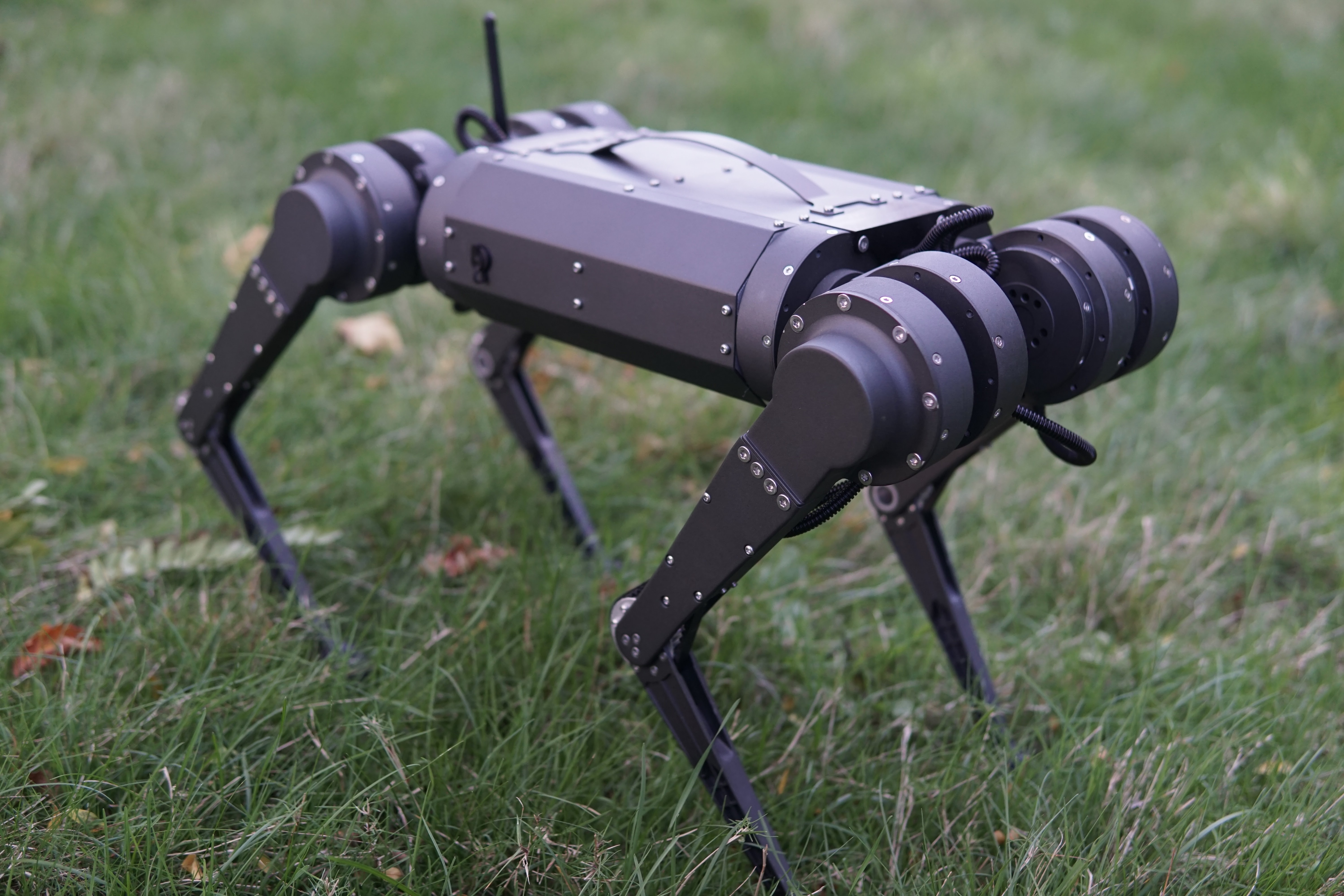
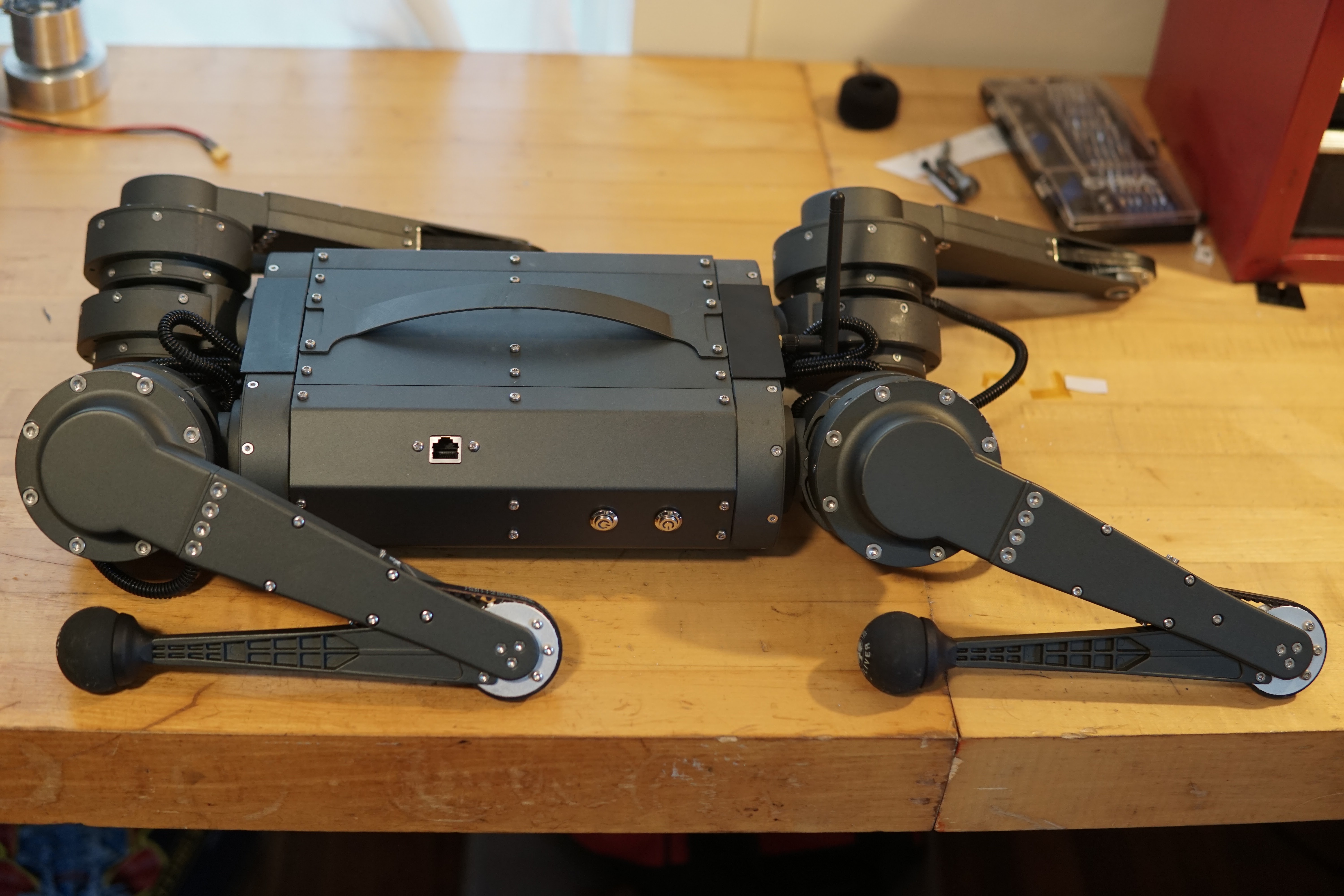
And here it is:


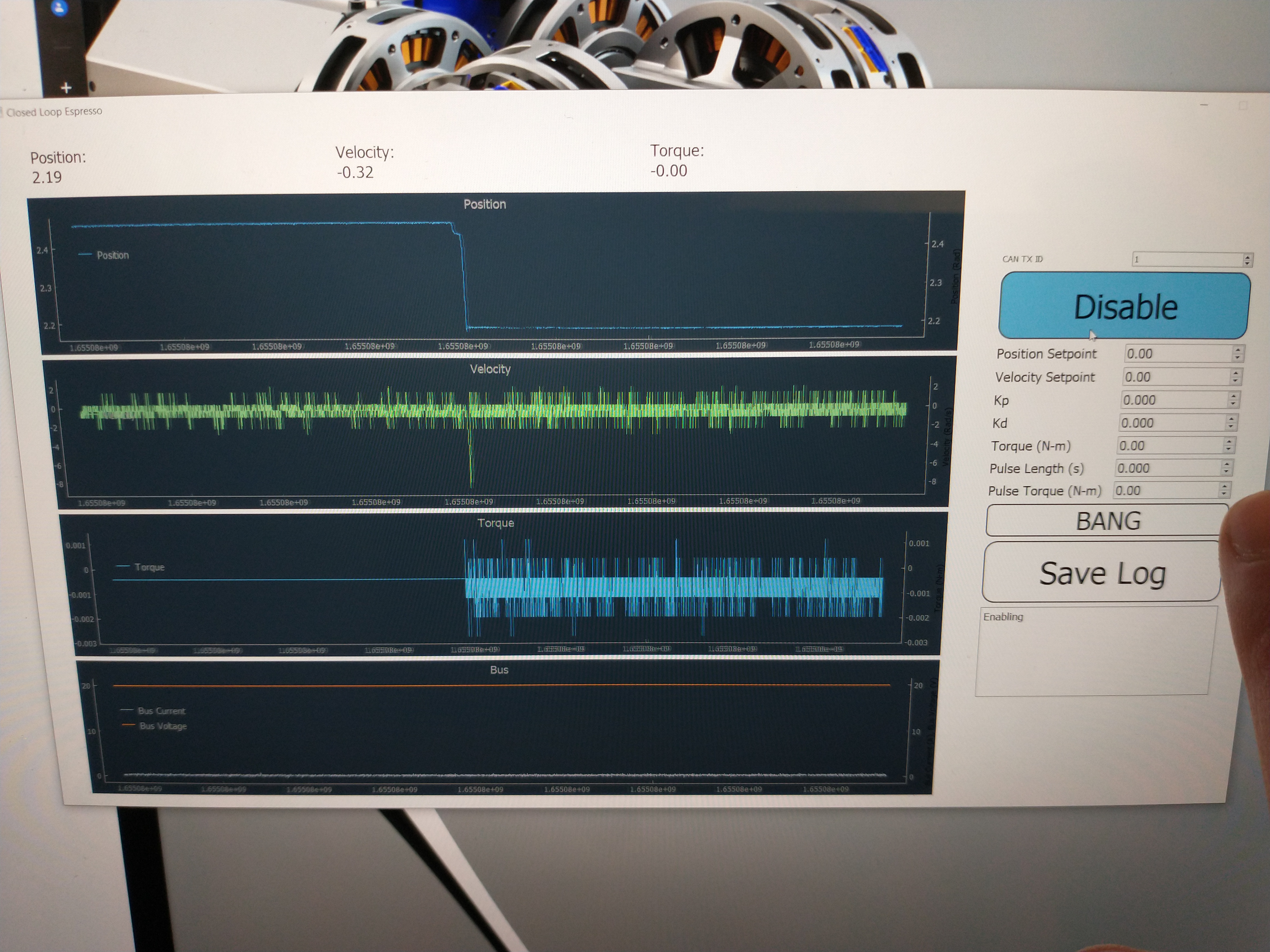
First power-up after reading the manual:


We have some miniature sheep (Ouessant) out behind my house (not my sheep, the owners of the property rent out the field out back).  I was curious how they'd react to the robot:


The backflip didn't work in the video above, where the battery was nearly dead, but worked once it was charged:


Since the robot works, time to take it apart.  On the operating table:


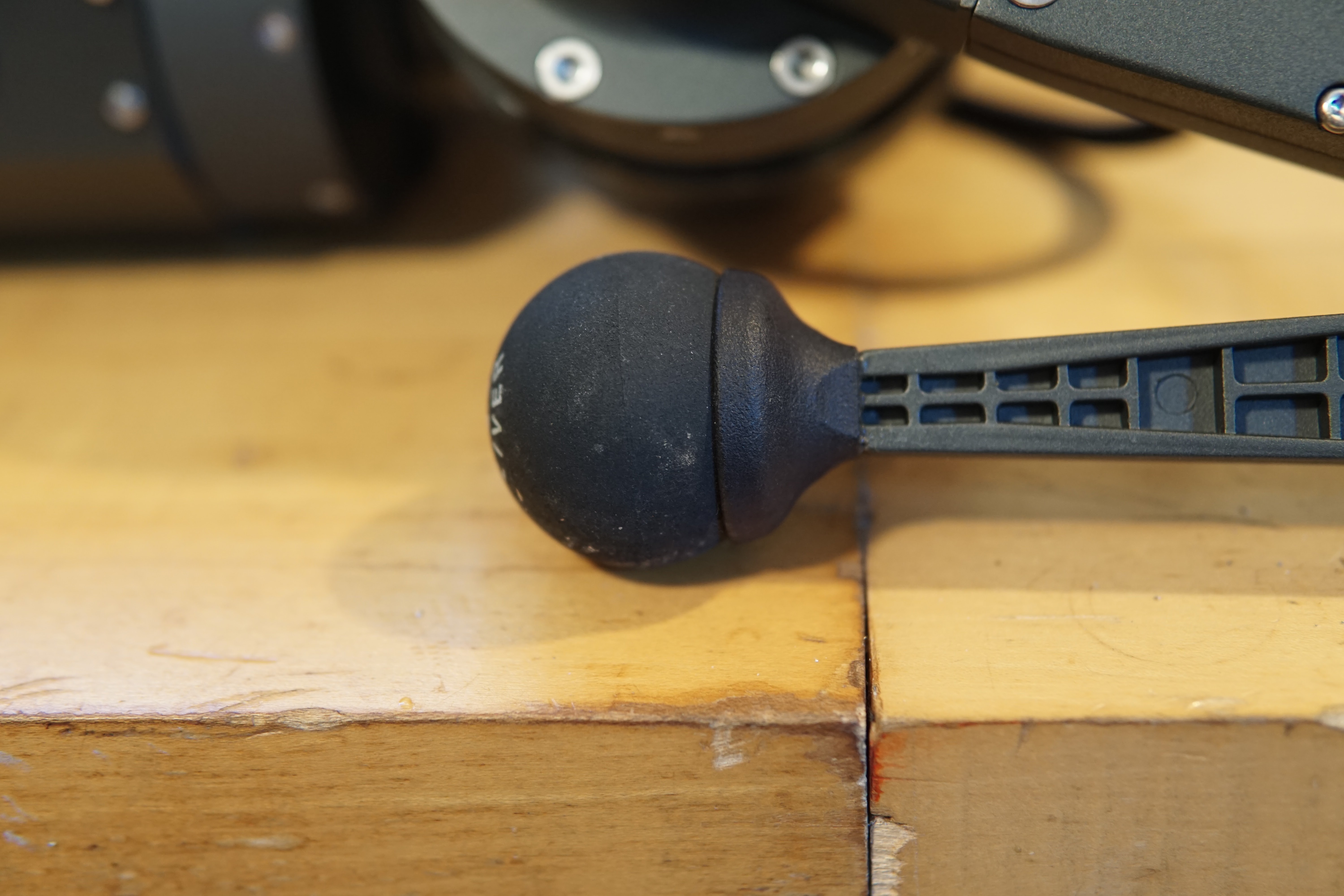
First hilarious mechanical detail, the feet are still squash balls:


The squash balls are stuck onto some SLA printed "socks", glued onto the lower leg  - just the way I did it on the original robot.  The later robots I made had easier to replace feet.


The major leg and actuator structures are all die cast!  Visible ejector pin marks:


Cracking the leg open - the robot has a 3-piece leg upper design, which on the original Mini Cheetah was a relic of the design of the teleoperation setup I built, which had one actuator on each side of the leg.  I originally thought the Mini Cheetah legs were going to have the same layout, but I ended moving things around.  But I'd already machined all the leg parts myself on the lab Haas, so I wasn't going to re-do all that work.  Amusing that they just copied this instead of doing a simpler 2-part clamshell like I did on the later robots.


More molding marks inside the upper leg structure:


The knee belt isn't a Gates belt like I used, and has fiberglass tensile members rather than Kevlar.  A few spare belts were shipped with the robot, that's probably why.  


Close-up of one of the belt tensioners - the roller is a drawn cup needle roller bearing, which isn't great since it doesn't evenly support the full width of the belt.  Tensioner looks a little anemic too, I wouldn't be surprised if they get bent (especially if the belts are upgraded to kevlar).  After breaking the first set  of tensioners on the original Mini Cheetah doing backflips, I made them way beefier and 7075.


One kind of neat change, the actuators have mounting features built-in so they can be axially stacked at the hip.  


Cracking the cap off the motor drive - more die casting:


Close-up of the motor drive.  It uses the same STM32F446RET6 micro and DRV8323RS gate driver I do, but different FETs and passives.  The power and CAN wiring are hard soldered into the motor drive PCB - I'm not a fan of that.  


There was a surprise on the underside of the motor drive - in the middle is an AMS AS5047 encoder IC (one I've used in the past but switch away from due to availability), but circling the encoder is another board with an array of analog hall sensors:


Through these holes in the rotor, you can see the corner of a bar magnet - the magnet is glued to the back of the planet carrier, on the output of the actuator.  This is actually a pretty neat trick - the analog hall sensors and bar magnet give rough output position - accurate enough to determine which rotation the input encoder is on relative to the the output.  For the Mini Cheetah, I didn't have any sort of output encoder, so the robot had to be turned on in a zero-configuration, within one rotor rotation (60 degrees at the output).  That would be totally unacceptable for a product, so it's neat to see this cheap solution that doesn't use a full-fledged output encoder. 


Cracking the covers open - looks like a bit of a wiring mess in there:


Closer view of the power management board.  In addition to the precharge circuit, there are a few interesting features here that I didn't have.  First, there's bus current sensing and over-current protection.  The big bug-like component on the right of the board is an Allegro hall effect current sensor.  The two DIP switches let you set the current limit (or turn it off, as you need to do for backflips...).  Also neat, there's an STM32F103 on the board, and an isolated CAN circuit copied from the SPIne board.  The CAN connector isn't populated, and I don't know if the micro even has any firmware on it, but presumably you could hook this into one of the CAN busses and log battery voltage and current.


Here's the robot propped up in a pin-up pose for accessing the side panel screws.  A pose the robots were frequently in for (dis)assembly back at the lab.


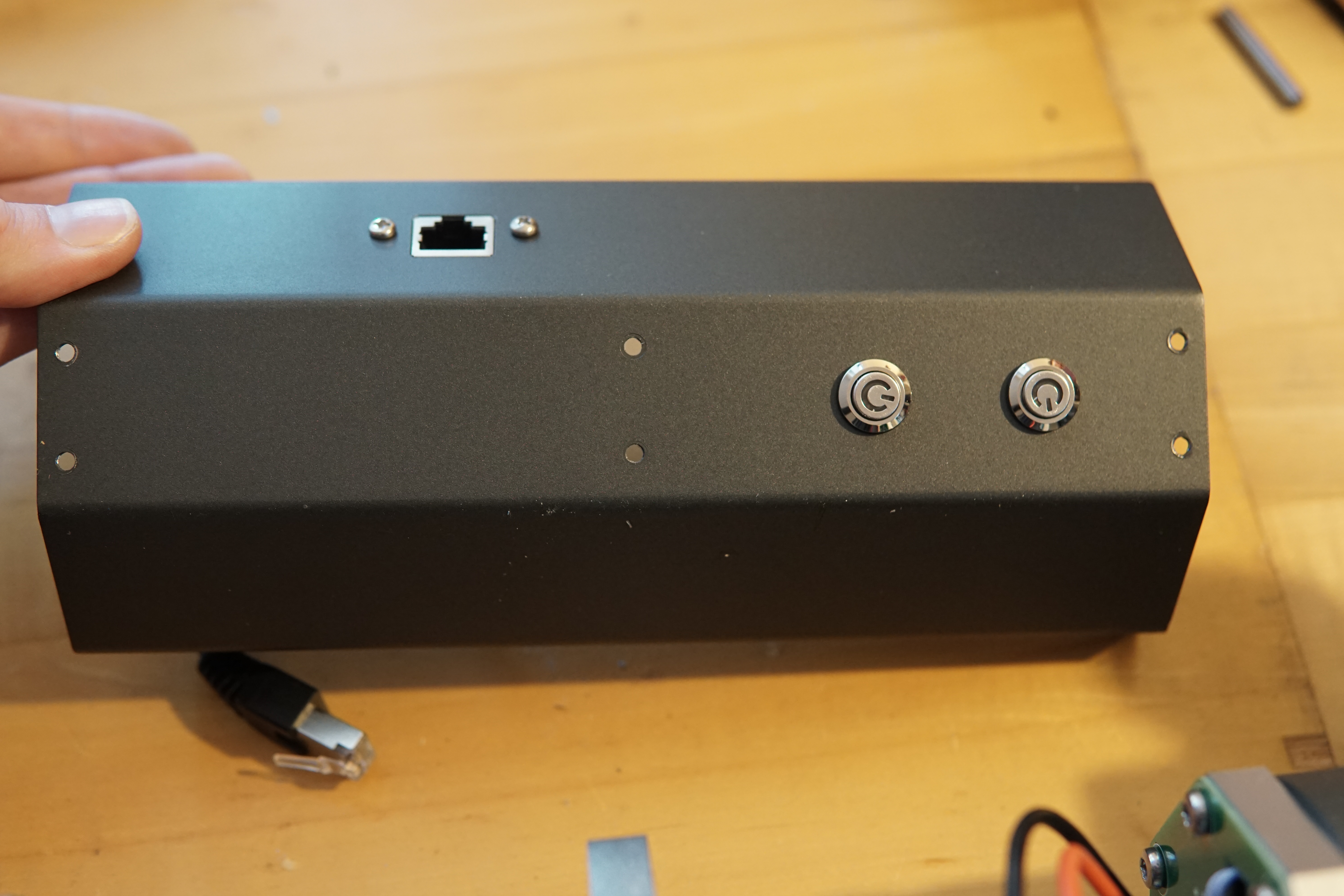
Nothing too exciting on the panels - a pair of switches for motor and computer power that plug into the power boards, and a chassis mount ethernet extension plugging into the computer


The battery on this robot is integrated rather than swappable (I guess you can't ship off-the-shelf drill batteries in a product), so there's a charging port on the outside:


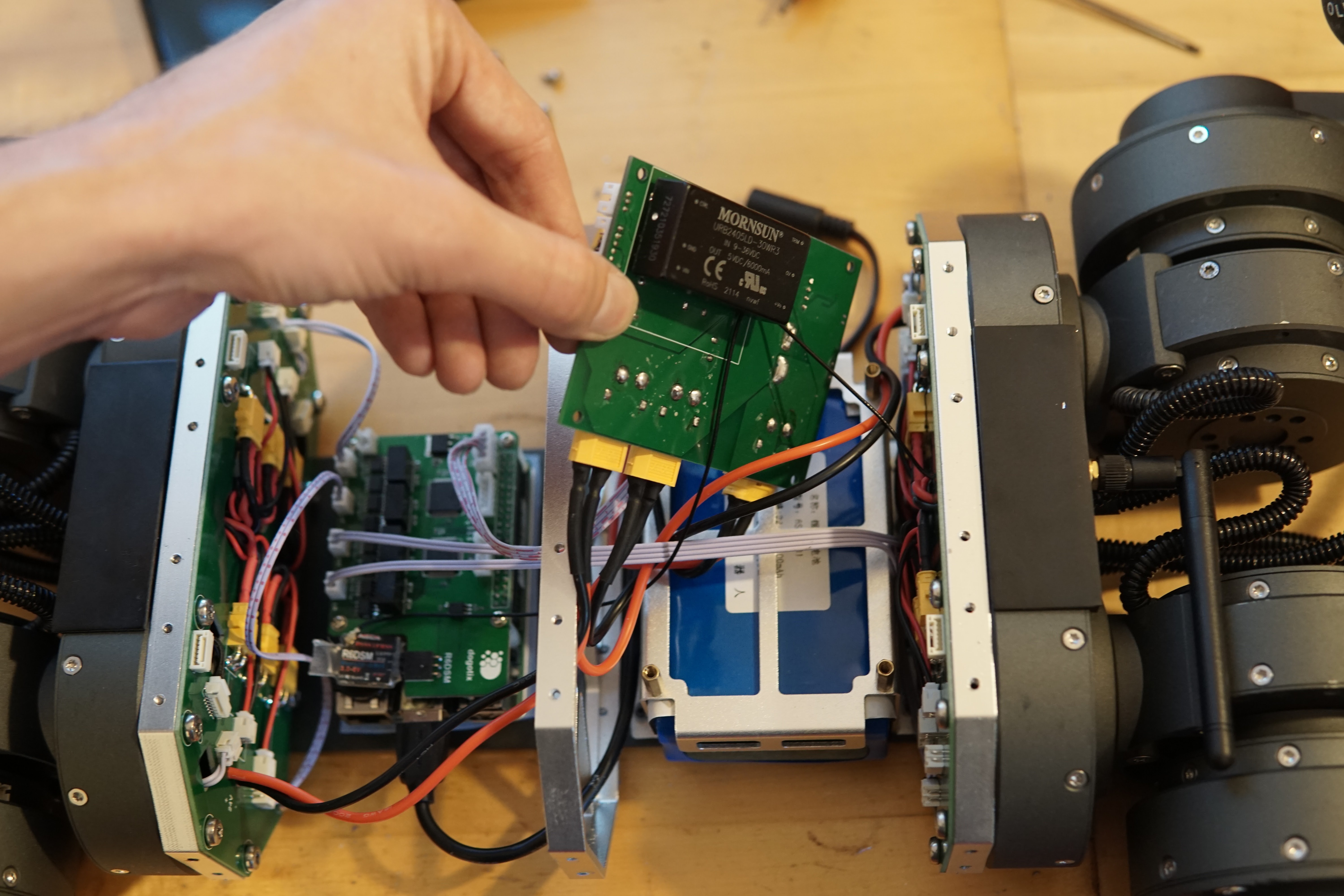
All the panels removed.  Blue battery visible under the power board:


Rather than wiring harnesses from the legs straight to the power board, there are power/CAN distribution boards on both ends of the robot, with one XT30 connector and CAN connector per motor:


The computer (UP Board) and SPIne board (SPI to quad-CAN interface) is nearly unchanged from my design.  Curiously, they aren't running the CAN grounds to the actuators, even though the CAN interfaces are isolated.  I haven't probed around too closely, but it sure looks like the CAN transceivers on the computer side are just floating.  Seems kind of sketchy. 


Pulling off the power board I found this funny assembly issue - the coax cable running from the RC receiver to the antenna on the back of the robot somehow got snaked through the leads of the isolated power supply powering the computer:


6s LiPo battery built in - I didn't take it apart any further than this:


I was expecting a cell-phone grade IMU in this thing, but it actually has something kind of expensive, a YIS300.  Never heard of these before, but it seems similar to the Vectornav or Microstrain IMUs I used, with an on-board orientation estimate.  These seem to be a few hundred dollars at least on AliExpress, so not cheap.  The hot-glue based micro USB connector retention is... questionable.


That's about it - I didn't want to recalibrate anything, so I didn't take the actuators fully apart.  I don't have any concrete plans for the robot, but I'm sure it'll show up again here.


July 10, 2022

Varying Pitch Screw Robot: Finishing the Mechanism and First Tests

Here's the detailed post to go with the pictures and videos I've been dribbling out over the last few months.

Last episode the mechanism was mostly finished, and was just missing the guide rollers that constrain the screw to linear motion and react the motor torque on the screw.

Looking at the CAD cross section, there are 3 sets of 3 rollers ride in shallow axial grooves on the screw.  The roller are spaced so that the screw is always supported, even as the rollers pass over the spiral grooves in the screw.  In the cross-section below, the red things are pairs of flanged bearings supporting the rollers.


The bump on the outside of the rollers was turned with a custom-made form tool.  I machined the form tool on the CNC mill out of a piece of (allegedly) high speed steel.  First I tried on a high speed steel lathe tool blank, but the small un-coated carbide endmill I tried with didn't last very long.  I dug through my bin of lathe blanks and broken end mill shanks, and tested the hardness of a bunch of pieces against the lathe blank that foiled my first attempt.  I found the shank of an old Harbor Freight HSS end mill, which was (perhaps unsurprisingly) appreciably softer than all the other pieces of HSS I had lying around.  But the rollers are plastic, and I was making ~10 of them, not 1000's, so it was still hard enough. 

I prepared the endmill shank on one of the MITERS Bridgeports - milling the rounded sides flat, and cutting in a top rake and front clearance angle:


I stuck the tool in the CNC mill to cut the profile:


And here's a close-up of the final tool and  one of the machined rollers:


The axles for the rollers are undersized (h8 tolerance) dowel pins, which are a nice slip-fit into the bearing IDs.  The fit between the dowels and the machined aluminum support piece is close enough that the pins can be pushed in and out by hand, but the friction is enough to keep them put for testing.  They'll be permanently held in place by a drop of retaining compound on one side, which should still let me press the pins out if I need to.


With the rollers made, the mechanism was ready for testing under power.  I was a little worried about commutation with the motor encoder offset through a 1:1 spur gear pair, but it worked fine.  The first test was to apply a constant torque and make sure the mechanism felt smooth throughout its travel.  


Things felt good, so next I put it into closed-loop position control and thrashed the leg back and forth.  I didn't notice until I filmed this video that the regen during acceleration was boosting the output voltage of the power supply up to >40V.  I was lucky the motor controller didn't get toasted.


During this testing I accidentally crashed the screw into the hardstop without a bumper - the cam followers ran into the end of the cam slots, so all the kinetic energy in the rotor went into shearing off the guide rollers.  I remade all the rollers out of PEEK to give them a bit more strength.  New PEEK one in black on the left, white delrin one with a chunk missing on the right:


For high power testing, I put together a simple test fixture for launching a steel puck the same weight as the final robot will be (hopefully).  The classic way robot-folk do their first leg tests is on a vertical linear rail, but a multi-meter tall rail wouldn't be very practical.  So instead of having the robot jump, it throws something of equivalent weight.

The screw mechanism mounts to a pair of machined plates and aluminum extrusions left over from the CNC mill enclosure.  A cart rides the rails with the same type of v-groove wheels some 3d-printers use.  The cart cradles a puck of stainless steel until it reaches the end of its travel, at which point the cart crashes to a stop and the steel puck is ejected.

Here's the test fixture, with electronics and batteries zip-tied to a piece of acrylic.  The electronics are just a Nucleo and a CAN transceiver - the Nucleo talks to the motor drive over CAN, and to my laptop over USB:


The picture below shows the v-rollers and matching groove in the aluminum extrusions:


Rather than building some elaborate stand for the apparatus, I bolted on a couple wooden stakes and rammed the test setup into the ground:


On the software side, I threw together a quick python GUI based off the espresso machine software.  It lets me save logs, manually set gains and commands, and send short torque pulse commands with the "BANG" button:


The first couple times I set up outside I had mysterious electrical issues - sometimes, when the motor was enabled and switching, the USB communication to the laptop would drop out and not come back until the Nucleo was power cycled.  Eventually I traced it back to the USB hub I had the Nucleo plugged in, but the issue was very intermittent and only showed up when the motor was powered with over 25V.  Once I ditched the USB hub, everything worked reliably.  Here's the first outdoor testing video:


This testing only got to about 3.3 meters, not the ~9 meters my original transmission ratio optimization predicted, but there were a few things going wrong.

One problem was pretty clear from the logs - once the motor gets up to about 7000 RPM, current tracking goes terribly wrong.  I think this is from the overcurrent protection on the DRV8302 gate driver on the motor controller triggering and turning off the FETs briefly before re-enabling, but I don't (currently) log the faults, so I'm not sure yet.

The motor speed only reaches ~700 rad/s vs the 1200 it's supposed to reach, which checks out in terms of the final height the puck reached.  


Another issue is that the motor isn't actually producing the torque I expect.  I got these custom-wound from T-Motor and it seems like they were off a bit - the torque constant measures out to be about 30% lower than I expected.  Sadly the motor in the mechanism right now is potted in, so I can't rewind it, or even remove it without some serious effort.   I've already cranked up the motor drive peak current to 60A from the 40A I usually run, and I'd have to turn in up to ~80A to get the torque I was expecting, and I'm a bit hesitant to do that.  But even with the torque constant being off, it should be able to launch a lot higher given the current control issues during most of the stroke.