a.k.a.
HobbyKing Cheetah.
Bear with me, this is going to be a long one.
Tl;DR:
I characterize a bunch of cheap brushless motors to investigate their usefulness in small running robots. Each motor gets a mechanical teardown and brief characterization. Scroll to the bottom for conclusions.
Background
I've worked on small running robots
in the past, in the
Biomimetic Robotics Lab. That robot was designed to be extremely low-cost, built out of super cheap off-the-shelf DC gearmotors, which proved to be a hugely limiting factor in terms of the kind of running the robot was capable of.
So here's the basic idea: The hobby remote-control-things market has produced an abundance of cheap, light, super powerful motors. This type of motor has showed up in my fleet of
small electric vehicles, and many other people's vehicles, multi-copters, airplanes, etc. long before me. But not in robots as precision or fast, torque controlled actuators.
There are a couple reasons for this, I think. First, suitable motor controllers don't really exist. There are super expensive small brushless controllers made by companies like
Maxon, and slightly less expensive (but larger) industrial-grade servo drives by the likes of
AMC. These could be convinced to work by appending your own sensor array to a hobby motor. However, these motors tend to be wound for low torque constant, low resistance, low inductance, so they want lots of amps and relatively few volts, which doesn't play nicely with the fancy servo drives. On the other end of the spectrum, there are the hobby grade controllers which usually are awful for anything other than RC vehicles, as they lack any form of current or torque control.
As I'm interested in using these motors in dynamic running robots, all these motor control options become even less useful. The fancy industrial drives might output 10 amps all day, but won't give you a drop more than 10 amps ever. For running, on the other hand, that's not what you want. Instead, you want many times your continuous current for short bursts and much less current the rest of the time. So more dynamic current limiting is required.
Thanks to
Nick's last semester at MIT working on the
Derpbike (a.k.a
Bremsthesis), I'm making this a senior thesis project. While I technically don't need to do one to graduate as I'm doing course 2A (the flexible MechE option), it's an excellent excuse to spend all of next term at
MITERS working on my own project
for credit. My end-goal for the semester is to get all the necessary motor control stuff worked out and build a prototype 2 degree-of-freedom leg using hobby RC motors.
Motor Characterization
I've started out this project by acquiring a pile of small brushless motors I thought would be suitable for this kind or robot, and characterizing them to figure out which are the best. These were visually narrowed down from the vast array of available motors by geometry. In general, pancake-shaped (large diameter, small depth) is best for high torque density
1.
This can be seen with a little motor dimensional analysis. Assume your rotor and stator are two rings of constant thickness, and radius and depth can be varied (not too unreasonable, although not all-encompassing). Motor torque will be proportional to both air gap surface area and air gap radius. So for a fixed air gap surface area (which means fixed mass, in this case) increasing diameter means increasing torque per mass.
Obviously there are many practical reasons why this might not be perfectly true (motor supporting material mass may scale differently, thinner motor means larger percent of windings in the end turns, etc.) but it's a good place to start from.
Here's the pile of motors I ended up with. From left to right, the Turnigy HD 5208 Gimbal Motor, Turnigy Multistar Elite 5010, Gartt ML 5208, Turnigy Multistar 4830, Turnigy Multistar 4822, and Flycat i-Rotor 5010:
Methodology
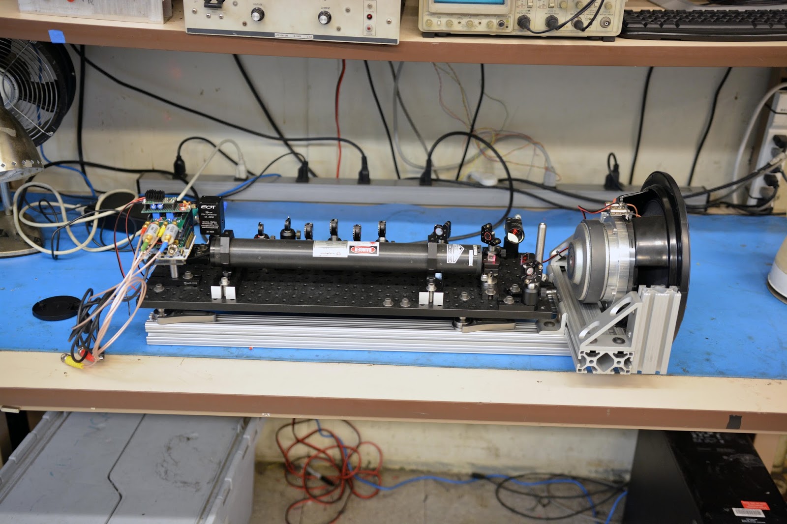
The goal of this motor characterization is to get a good first-order understanding of each motor's electromagnetic performance, as well as gauge the quality of construction and ease with which these motors could be adapted to legged robot applications. All the characterization was done with a benchtop power supply, a pair of multimeters, a cordless drill, and an oscilloscope:

The two parameters I measured were line-to-line resistance and line-to-line back-EMF waveform at constant speed (hence the cordless drill). From these numbers, I can calculate the torque constant (Kt) and "motor constant" (Km) by finding Kt/sqrt(R). This number tells how much torque a motor can produce for a given amount of power dissipation in the windings (the units also work out to N*m/sqrt(watts). It is important to note that this number is independent of how the motor is wound (assuming constant pattern and same amount of copper). In other words, rewinding a motor to have twice the turns will give it twice the torque constant and four times the resistance, meaning the motor constant is unchanged. The motor's ability to produce torque (looking at just resistive loss) is not dependent on how high or low a torque constant it is wound for, if copper area is held constant. I find this to be a common point of confusion.
So, motor constant is a very limited motor performance metric, but if you just want a good idea of how much motor you have, it's a useful number.
Furthermore, perhaps a good metric of how well your motor's materials are used to produce torque would be Km/sqrt(mass). Sticking two identical motors end to end would double the mass and increase the motor constant by a factor of sqrt(2), so this number would remain constant.
Turnigy HD 5208 Gimbal Motor
Link
Price: $39.20
The rotor is axially constrained by a single e-clip. The shaft and bearings are very small diameter, and there's no extra shaft sticking out of either end.
There is plenty of space for more copper on the stator. The windings are a single strand of very fine wire.
Extra-thick laminations. Another indication that this motor wasn't designed to spin fast:
Nice thick magnets. There's no visible balancing done to the rotor.
Back EMF on the scope: This is nominally a 31 RPM/Volt motor.
Torque Constant: 0.3081 N*m/A
Resistance: 11.7 Ω
Motor Constant: 0.0901 N*m/sqrt(watt)
Turnigy Multistar Elite 5010
Link
Price:
$52.69 $42.15 as of 1/29
This is a beautiful motor. You pay for it, but Hobbyking really outdid themselves here. For an extra $15 over other motors of similar size, you get absolutely beautiful single-strand, perfect windings, curved N45SH magnets, and an overall just really nice feeling motor.
Solid construction all around. Big shaft and bearings. Shaft axially constrained by a locktite-ed screw.
Rather disappointingly, there's a lot more space for copper on the stator. However, I think for multirotor-duty, this actually is a good thing. I bet these motors are exceptionally well cooled with air forced past them by propellers, considering the thick, clean windings and room for airflow between stator slots. Also take notice of the tapered ends of the stator teeth. Every other motor tested has right angles at the ends of the stator teeth. Hard to say what this does without seeing the FEA.
As expected, it has nice, thin laminations:
A closer look at the curved magnets. Also some small daubs of blue balancing goop.
Drill-o-metered back EMF. This is nominally a 274 RPM/Volt Motor. Fairly sinusoidal looking.
Torque Constant: 0.0333 N*m/A
Resistance: 128 mΩ
Motor Constant: 0.0930 N*m/sqrt(watt)
Gartt ML 5208
Link
Price: $38-$45
I had high hopes for this motor. I managed to offer them down to $38 on ebay, making it cheaper than most equivalently sized motors from Hobbyking. Unlike the two motors above, it has 22 rather than 14 poles. A nice thing about having more pole pairs is that there's less flux between poles (because each pole is smaller area). I was hoping this would mean that the rotor can would be less leaky (i.e. less flux leaking out of it). This indeed appears to be the case - you can barely feel metal objects stick to the can of the motor.
Solid construction here too. Again, big bearings, big shaft, snap ring and screw to axially retain the rotor. The magnet fill is pretty low though.
The windings are "Hobbykinged" with a bundle of parallel strands. Cleanly done, though. The cutouts in the stator between the bearings and the windings are interesting.
Nice thin laminations:
More balancing compound, and a better look at the magnets:
Back EMF. This is nominally a 340 RPM/Volt motor. Some much more noticeable harmonics on this one.
Torque Constant: 0.02498 N*m/A
Resistance: 97.5 mΩ
Motor Constant: 0.0800 N*m/sqrt(watt)
Turnigy Multistar 4830
Link
Price: $43.29
This motor has a different aspect ratio than the rest of them - longer axially, smaller diameter. Like the one above, it's a 22 pole motor. Rather annoyingly, it came in a fancy metal box with foam cutouts on the inside. I'd have preferred cheap cardboard packaging and a couple dollars less expensive motor.
Well constructed here. Not sure why so many washers at the end of the shaft, but like before it's a screw plus snap ring to hold the can on.
Good magnet fill, and a little balancing done to the rotor:
Eww, some big 5th harmonic in that back EMF. This is nominally a 420 RPM/Volt motor.
Torque Constant: 0.0212 N*m/A
Resistance: 102.8mΩ
Motor Constant: 0.0662 N*m/sqrt(watt)
Turnigy Multistar 4822
Link
Price: $32.91
I was expecting this motor to just be a shortened version of the 30mm motor, but there are a surprising number of changes between the two besides the stator length.
The rotor retention is different - this one just has a snap ring, while the 30 mm one had a snap ring and a screw-on cap to the shaft:
The bearings and shaft are also smaller:
As usual, there's some balancing goop on the rotor:
I was expecting the back EMF waveform to look pretty much the same as the 30mm version of the motor, but to my surprise it showed none of that 5th harmonic, and was very sinusoidal. Not sure what's going on here to cause the difference between the two. I can't imagine the winding pattern is different between the motors. This is nominally a 390 RPM/Volt motor.
Torque Constant: 0.0223 N*m/A
Resistance: 205 mΩ
Motor Constant: 0.0493 N*m/sqrt(watt)
Flycat i-Rotor 5010
Link
Price: $14.49
With its $14 price point, this motor is the odd one out. I got this motor because I searched "5010 Brushless Motor" on ebay, and didn't read the description carefully enough. Usually, "5010" means the motor has a 50mm diameter, 10mm tall stator. For this motor, those are the outer dimensions. The actual stator is much, much smaller. No surprises here, the motor is smaller than the others, and construction quality is about as awful as you would expect for a $14 motor.
Nice exposed underbelly. Makes it lighter, right?
The rotor is axially retained by a retaining ring and bronze washer. I managed to send the retaining ring flying across MITERS never to be seen again. I can't say I'm particularly broken up about the loss. Small diameter bearings and shaft.
Messy single-strand winding. More or less as expected.
Despite the lack of visible balancing, the motor was okay sounding when I spun it up with an RC airplane controller.
Back EMF. This is nominally a 360 RPM/Volt motor.
Torque Constant: .0249 N*m/A
Resistance: 286 mΩ
Motor Constant: .0497 N*m/sqrt(watt)
Conclusion
Here's a nice table:
Motor
|
Torque Constant (N*m/A)
|
Resistance (mΩ)
|
Motor Constant (N*m/sqrt(watt))
|
Mass without leads (g)
|
Price ($)
|
Turnigy HD 5208
|
0.3081
|
11,700
|
0.0901
|
167
|
39.20
|
Turnigy Multistar Elite 5010
|
0.0333
|
128.0
|
0.0930
|
183
|
52.69
|
Gartt Ml 5208
|
0.02498
|
97.5
|
0.0800
|
173
|
38.00
|
Turnigy Multistar 4830
|
0.0212
|
102.8
|
0.0662
|
162
|
43.29
|
Turnigy Multistar 4822
|
0.0223
|
205
|
0.0493
|
100
|
32.91
|
Flycat i-Rotor 5010
|
0.0249
|
286
|
0.0497
|
90
|
14.49
|
The real competition here is between the top three motors - the Turnigy gimbal motor, Multistar Elite, and the Gartt. The bottom two are bit smaller than the size range I'm interested in, and the Multistar 4830 is strictly worse than the others for similar cost and weight.
Rather to my surprise, just from numbers, the Turnigy Gimbal motor does quite well. A solid second in terms of motor constant, lighter than its two competitors, and basically the same price as the Gartt. From feasability of using in a robot, though, it doesn't look so good. To get equivalent performance from the gimbal motor to a, say, 20 V system with the other two motors, I'd need a 200V bus! Not too tasty. Its mechanical construction is generally worse than the others, as well. So the conclusion is....unclear. The Multistar Elite is just so nice... the extra 40% cost over the Gartt seems palatable when considering the overall cost of building a robot. 18% larger motor constant, back EMF is more sinusoidal, thermal performance I'd guess is better (although I have done no analysis or experimentation to back this claim up), and it just
feels nice.
**Edit**
As of 1/29/2016, the Multistar Elite motors have dropped to $42.15, making them a clear winner in this motor shootout.
****
Next steps: I have already designed and laid out motor controller hardware (for now as a Nucleo shield. Once I get control stuff working I'll put the micro on board), and will send out for boards and parts from digikey shortly. Then I can get crunching away on motor control. I still need to decide on position sensing method.
There's also a lot of mechanical design work that needs to be done to integrate these motors into legs. Like the full-sized cheetah robot, I'd like to use a single state planetary reduction, so that needs to get figured out.
Stay tuned. This is gonna be good.