December 21, 2018

Planar Magnetic Headphones, Part 3: Finishing Up

Over a year later, I've finally finished up the planar magnetic headphones.  They even sound decent.


Here's the rest of the build log:

The change that got them from sounding terrible to sounding tolerable was reducing the tension in the membrane as much as possible.  The first few test versions were intentionally tensioned, which turned out to be a bad idea, causing weird notches and resonances in the frequency response.  The new membrane is glued to a frame under no tension.  I also switched to an even thinner flex pcb material, Pyralux AC 091200EV, which has a 12 micron kapton layer, 9 micron copper layer, and no adhesive.

After the toner transfer.  Getting the toner transfer right without wrinkling the material was tricky:


After etching.  The driver came out to about 50 ohm resistance.


This time I glued the membrane to a fiberglass frame.  To get the PCB flat without tension, I stuck it down to a metal plate by wetting the plate.  I forgot to take a picture of these assemblies, but here's one of the original PCBWay flex pcbs glue to an identical frame:


For the final headphones I'm using a single sided magnet array - I first built a single driver, and did experimenting with both single and double arrays, and qualitatively could not hear any significant difference between the two.  And a single array is about half the effort of the double array.  Here's the test-driver, with a plastic back, and the first ultra-thin board I was able to successfully etch:


I machined two new aluminum backs, and stole the headband from a cheap pair of headphones.  Maybe eventually I'll get around to making a nice headband, but for the time being I'm not particularly interested in building headbands:


On a dummy head:


They sound decent.  They're a bit bass-heavy, and require some equalizing, but once that's done I quite like them.

December 1, 2018

CORE Outdoor Power PCB Motor Teardown

A company called Core makes some unusual electric lawn tools based on axial flux PCB motors.  I first heard about them several years ago, and finally picked up one of the motors to take apart.

Here's the weed-wacker.  I just got the head of the tool- they make a base called the "drive unit", which holds the battery and electronics.  Each head has its own motor:


The motor's right at the end, direct driving the spool of wire:


Removed from the stick.  Three board-mount faston terminals for phase power, and another connector for hall sensors.


The motor was a huge pain to take apart, as it is pretty much entirely held together with retaining compound.  With a hammer and some screwdrivers I was able to pull off the back cover:


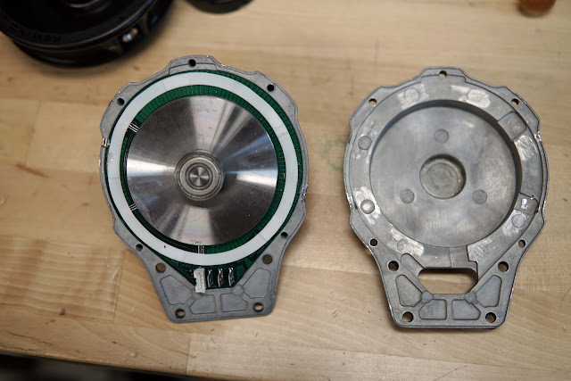
The shaft and front bearing were pushed out of the other half of the housing with a gear puller.  There's a ring of thermal pad on one side of the board:


It's a dual-rotor design, with the PCB stator sandwiched between the two halves of the rotor.  The rotor is held together by even more retaining compound:


To pull off half of the rotor, I gripped it in a small lathe chuck and used  a gear puller to pull it off the shaft:


First a closer look at the stator.  The board had at least 4 layers, and probably has 4 oz copper - it's very dense feeling. 

Some observations and thoughts:

- Each phase has 4 4-turn coils, and the 3 phases are overlapped.   This is a full-pitch winding.
- This winding pattern results in a large area of end-turn, so the actual "active" area of the stator is unfortunately small - less than half the area of the PCB actually produces torque.
- The traces neck down and become thinner within the active area.  Presumably this is to reduce eddy current losses from the magnets swinging over the traces. 
- The hall sensors are through-hole halls, surface mounted sideways into cutouts in the PCB, so they add almost no additional thickness.
- The empty space around the edges of the board are filled with radial strips of copper.  I'm not really sure why.  Maybe for thermal reasons?  The edge of the board is heatsinked to the aluminum housing through a ring of thermal pad.

Here's the patent for reference.


The two rotors have single-piece magnets magnetized with 4 pole-pairs:


One of the reasons it's all held together with retaining compound is that the bearing bores in the castings aren't even post-machined.  The bearing is just glued straight into the rough, tapered hole in the casting:


Back-EMF is pretty sinusoidal.  An FFT reveals a little bit of 5th harmonic.  Flux linkage is ~.0044, for a torque constant of .0264 N-m/A (peak phase amps).  Line-to-line resistance is 125 mOhms. This gives a motor constant of .086 N-m/sqrt(watt).


Over all it's not a particularly high performance motor for it's size or weight.  There's a lot of dead space, and a very heavy, high-inertia rotor.