Showing posts with label Planar Magnetic Headphones. Show all posts

December 21, 2018

Planar Magnetic Headphones, Part 3: Finishing Up

Over a year later, I've finally finished up the planar magnetic headphones.  They even sound decent.


Here's the rest of the build log:

The change that got them from sounding terrible to sounding tolerable was reducing the tension in the membrane as much as possible.  The first few test versions were intentionally tensioned, which turned out to be a bad idea, causing weird notches and resonances in the frequency response.  The new membrane is glued to a frame under no tension.  I also switched to an even thinner flex pcb material, Pyralux AC 091200EV, which has a 12 micron kapton layer, 9 micron copper layer, and no adhesive.

After the toner transfer.  Getting the toner transfer right without wrinkling the material was tricky:


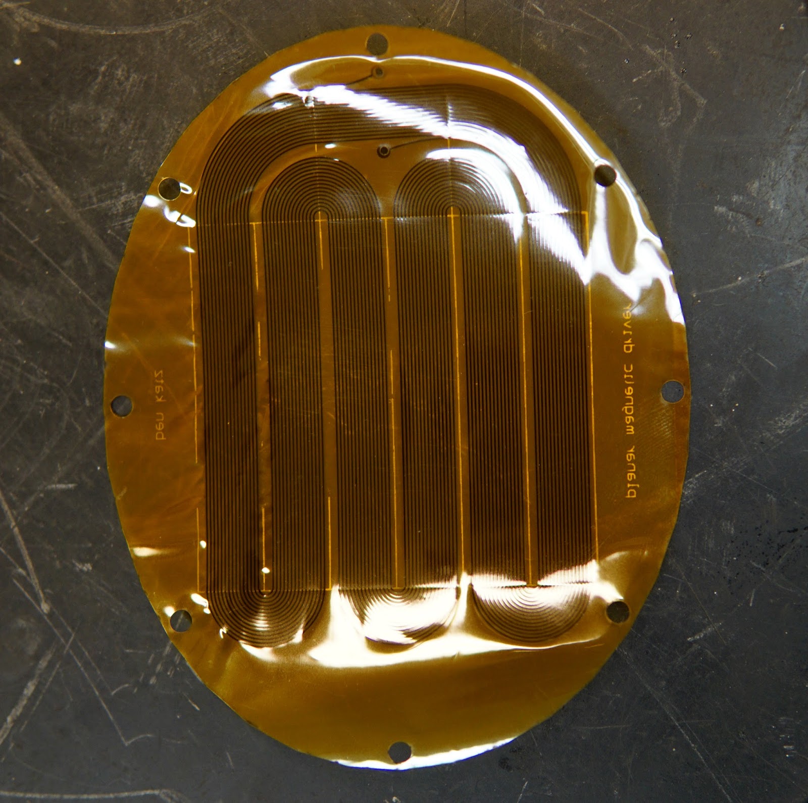
After etching.  The driver came out to about 50 ohm resistance.


This time I glued the membrane to a fiberglass frame.  To get the PCB flat without tension, I stuck it down to a metal plate by wetting the plate.  I forgot to take a picture of these assemblies, but here's one of the original PCBWay flex pcbs glue to an identical frame:


For the final headphones I'm using a single sided magnet array - I first built a single driver, and did experimenting with both single and double arrays, and qualitatively could not hear any significant difference between the two.  And a single array is about half the effort of the double array.  Here's the test-driver, with a plastic back, and the first ultra-thin board I was able to successfully etch:


I machined two new aluminum backs, and stole the headband from a cheap pair of headphones.  Maybe eventually I'll get around to making a nice headband, but for the time being I'm not particularly interested in building headbands:


On a dummy head:


They sound decent.  They're a bit bass-heavy, and require some equalizing, but once that's done I quite like them.

September 17, 2017

Planar Magnetic Headphones, Part 2

I finished putting together a housing for a single driver.  CNC milled aluminum goodness:

The machining was done in two operations.  All the fancy 3d profiling was done with the part flipped over and held in soft jaws.


Front side:


Back side, before gluing in the magnets:


Here's the assembled driver.  I'm using a cheap off-the-shelf pair of earpads.


This version sounded pretty terrible.  The pcbway flex-pcb was way too thick, making it both too heavy and too stiff.  The response was way to heavy at low frequencies, with a terrible ~100 hz resonance, and there were all sorts of weird notches in the frequency response.  But it did make sound, so that was a good start.

I ordered some Pyralux samples from Dupont, and tried etching my own drivers.  I first tried with the LF7012R variety, which has 1/2 oz copper, 13 micron kapton layer, and 13 micron adhesive.  I measured the total thickness to be 45 microns where there was copper, and ~25 microns without copper, which is half the thickness of the pcbway material.  At the time I thought that was their thinnest material, but I hadn't looked through their datasheets carefully enough.  The AC 091200EV material has 1/4 oz copper, 12 micron kapton, and no adhesive layer, so it should be in total something like 20-25 microns thick with copper, and 12 without.  I've got a sample of that on the way, and will report back when I've etched some.

After a few tries I figured out a pretty good process for etching the pyralux.  I did the classic toner transfer and ferric chloride etching method.  The etching part worked really well, but doing the toner transfer proved finicky.  It took a few tries with a few different laser printers to get the process to work.

Etched:


Assembled into the driver:


This one sounds much, much better, although there's definitely still a little weirdness going on.  Listening to it plugged into a function generator and sweeping frequencies, the low-frequency resonance is gone, and over all it's much flatter, but there are still some strange notches in the response.  Unfortunately I don't have a good setup for quantifying the frequency response at the moment, but it's definitely a little off right now.  But it's getting better.  I'm hopeful that the even thinner flex pcb material will improve the situation further.  Reducing tension in the membrane might help as well.


August 20, 2017

Planar Magnetic Headphones, Part 1

A brief break from 3-phase electric motors, for a different kind of electromagnetic actuator.

Planar magnetic (a.k.a. "orthodynamic", "isodynamic", etc) drivers are a pretty neat topology of linear motor, which, as far as I can tell, has found no application besides speakers and headphones.  Here's a well-diagrammed explanation of how they work.

Instead of a voicecoil actuator which drives a stiff cone back and forth, like a conventional speaker driver, a thin membrane with conductive traces sandwiched within a funny magnet arrangement moves back and forth.

image credit: innerfidelity.com
I won't try to argue that this is "better" than a conventional driver in any way, because frankly I don't care.  It is cool, though, and also a perfect excuse to send out for some flex-PCB's, which my go-to PCB vendor, PCBWay, recently started offering for quite reasonable prices

I started out by playing with magnet arrangements in FEMM, to see how sensitive this arrangement was to changes in magnet dimensions and spacing, and I ended up here:

This uses 1/8" square N52 magnets, with a 2mm airgap, and 9mm pitch.  The array 2 inches long (into the page), and each bar is a pair of 1/8" x 1/8" x 1" magnets, which are cheaply available on ebay:


Here's the tangential flux density (which is the normal force producing component)  in the middle of the air gap:


Doubling the depth of the magnets got it up to .5T peak (the path around the magnet gets longer, so less flux leaks through it), but I decided it wasn't worth the more than double magnet cost (they are harder to find magnetized through the small face).

Here's what the actual flex pcb coil looks like.  The traces go up and down in the regions of ±.35T field in the plot above.  This was very unpleasant to draw in Eagle.  0.25mm trace width with .5mm pitch.  PCBWay claims to be able to do .1mm between traces, but I didn't want to push it.


For the actual PCB, I chose single layer, 75µm flexible adhesiveless base, .1mm FPC thickness, no solder mask, and 1/3 oz copper, to keep the board as light and flexible as possible. Maybe a 2-sided trace would have been better, for a higher ratio of conductor to pcb material, but this whole thing is an experiment anyway.


Front:  A few of them came out a little wrinkly.  Not sure why, or if it will cause problems.  In retrospect, it might have been a good idea to put a thick copper trace around the outside of the whole board, to stiffen up the perimeter.  Coil resistance came out to 16 ohms.


Back:


I CNC milled half of a housing out of some Delrin:


Glued in the magnets:


There's a lip on the housing that will apply some tension to the flex pcb to hold it flat, once both halves of the housing are made, but it was secure enough for some testing with only one half.


It actually works even with only half of the magnet arrangement - half the magnet gets you half the flux density.  It should produce the same volume on roughly half the power, once the whole thing is assembled.


I'll reserve qualitative judgement until the whole thing is assembled, but from the brief testing I've done on this single partially assembled driver, it seems promising.