Showing posts with label Wooden Roller Coaster. Show all posts

December 28, 2014

East Campus Roller Coaster: Actually Building the Thing

Winter break means it's time to finally finish up roller coaster documentation.

TL:DR; here's a timelapse of the construction.  Jaguar setup and maintained a bunch of cameras, and I compiled the stills into video.


Construction took place over a week, and was done by a combination of East Campus residents, incoming freshmen, a few students from other dorms, and a few random strangers.

I think there are a few key things that made it possible to finish construction in such a short timeframe:

Being prepared
We thought through the construction process as thoroughly as we could before actually building anything.  This included putting together lots of documentation and drawings for different parts of the roller coaster, thinking through assembly order and methods, and making jigs to assemble some repetitive parts.  Here's an example of one of the sets of assembly documents.

Some parts of the construction, like assembling frames under the track, could be easily parallelized.  Each unique frame section got its own drawing showing the critical dimensions and pieces of lumber required.  These drawings could then be handed to one or two reasonably skilled people, who were generally able to assemble a frame section in a half hour or so.


Here's footprint drawing, showing the location of each of the frame sections (like the one above).


The frame directly beneath the track was made from two types of assembly which alternated and fit together kind of like a roller chain (wide link, narrow link, wide link, etc).  We built jigs for both the cutting of the 2x6s and 2x4s as well as assembly jigs, since many of each were needed.  Then the job was handed off to a crew of enthusiastic freshman who had never really used power tools before.


Not trying to do everything...
Basically delegate, delegate, delegate.  I like doing everything, so it's very tempting to try to personally do or oversee everything.  Turns out, with a project this big that just isn't possible.  Wesley was also great at organizing people to do things.  On that note, having more than one person who really knew what was going definitely sped things up.  

...But still trying to do as much as possible.
Jobs that were critical to the roller coaster's function and couldn't be easily farmed out Wesley and I did ourselves.  Laying the track sub-frame, putting up the tower posts, making sure the frame was actually straight, and more.  Sleep was scarce that week.

On to the actual construction.

The night before the first load of Home Depot wood arrived, we marked out the foundation of the roller coaster in cheap yellow rope and tent stakes.  The next day, we dug small pits for each of the concrete footers and filled them with gravel.  We then leveled all the blocks and started assembling the base platform:


By the first night we had the frame of the platform:


The next day assembly of the frame sections started.  They can be seen propped against the trees.  Unfortunately, I underestimated the amount of wood we would need over the first weekend, so we used up all our wood early and lost a day.


Sterritt Lumber to the rescue!  Truly absurd quantities of wood were delivered on an all-terrain three wheeled swerve drive forklift.


And at this point my documentation fell apart a bit because I forgot to take pictures during the chaos of construction.  

The tower posts were assembled to their full 28' length on the ground, bolted together, and then disassembled into halves.  The lower half of each posts went up immediately.  After the second level platform was built, the top halves of the posts were carried up and bolted on.  

Once all the frame sections were built, it only took one day to assemble them to make the structure beneath the track.  This was definitely the most impressive day of progress, with basically the entire structure appearing over the course of 8 hours.

Photo credit to Wesley Lau

To make sure the frame was assembled straight, each section of the frame was measured to the sidewalk parallel to the coaster.  Except for two of the middle sections which interfered with tree roots, we were able to get everything positioned plus or minus about a half inch from the sidewalk over the entire length.  The offset in the two middle sections was noted and compensated for when we put of the track sub-frame.  To prevent error accumulation along the length of the roller coaster, each frame section was measured and positioned with respect to the base of the tower, rather than with respect to the previous section.

Tall sections of the frame also had work platforms and railings built into them, so we wouldn't have to use ladders when working on or inspecting the track.


Putting up the posts and floors involved lots of miserable augering of 1" and .75" holes through up to 10" of solid wood.  Despite Rush's purchase of the biggest, highest torque drills that could be found at Home Depot, the 1" auger bits repeatedly got stuck in the 4x4's.  Unsticking them was a half-hour process of violently wrenching the bit back and forth until it came loose.  Next year I should build some sort of auger-assist device with a extra gear-down for the drill and a brace so your hand's don't have to deal with the drilling torque.

Photo credit Danny Ben-David

Putting up the track sub-frame was one of my favorite parts of construction - watching the roller coaster's track take shape was beautiful.  This was a job that had to be done serially, so Wesley and I did the whole thing.  To make sure each segment of the track was put up in the correct orientation, I made a drawing including the height of the end corner of each segment with respect to the beam supporting it.  We would tack in a segment to the previous one at a corner.  The segment could then be rotated to the correct height, and fixed in place with a second screw.  Vertical supports were put in for about every other segment.  Someone else came in behind us and filled out the supports later.  In all, laying the sub-frame was about a day and a half of work.


The track framing finished bright and early in the morning.


The ladder to the second floor was replaced with a nice shallow staircase.  The staircase was another job that was completely handed off to a dedicated crew with very little guidance.  A couple days later, a finished staircase appeared.


Laying the plywood track took a day and a night, finishing around 9 or 10 a.m. on the Sunday of the East Side Party.  The track consisted of three layers of 3/8" plywood bent along the wooden frame.  Bending the plywood turned out to not be too hard.  The most difficult bit to bend was the start of the first drop.  The upturn at the end of the track was another challenge, but that managed to work out nicely as well.  We had an awesome crew who worked through the night to finish laying the track.

Photo credit to Billy DeMaio

Photo credit to Danny Ben-David


Photo credit to Danny Ben-David (click to zoom for glorious high-resolution)

Photo credit to Rachel Davis.  Don't worry, the last 4 feet of plywood were added later.

Once the plywood track had been laid down, we slowly rolled the cart along the track, so make sure it traveled smoothly.  Then we did an unmanned test run with an empty cart, followed by a test run with 150 lbs of sand in the cart.  Then I got to go.   This was my first time riding a roller coaster of any kind.  It was awesome. 


At this point we hadn't put in the last 4 of plywood track.  The cart didn't quite reach it, but I thought it would be good to put in, if only to make people feel safer.

For the first day of operation, the cart faced forwards.  We tried flipping it around the next day, and people seemed to prefer going down backwards, so the ride was left backwards for the remainder of the week.

Photo credit to Danny Ben-David


Actually running the ride started out pretty inefficient.  A crew of 4 or 5 people would slowly walk the cart back to the bottom of the first hill, at which point we winched the cart to the start with an overvolted electric truck winch running off a big A123 battery pack, and cooled by a bank of server fans.  The process took about 8-10 minutes per run.  Later though, we improved the cart return process to use one strong person to get the cart back to the winch.  By the end, the total ride and reset time was under 3 minutes.  In total I'd estimate around 400 people were able to ride the roller coaster between Sunday night and Thursday afternoon, when we closed it down.

Photo credit to Wesley Lau

Here are a couple videos of rides from Sunday night (courtesy of Rachel Davis):


One big unknown pre-building was how the plywood track would hold up to repeated use.  By the time we stopped doing rides, there were a couple small patches of plywood where the top ply had started falling apart.  These patches were at the highest compression spots on the track, at the bottoms of the first two hills.  So the top layer of plywood is good for a few hundred ride cycles at this loading, but not much more.  If we did want to run the roller coaster for longer, however, it would have been easy to replace just the top layer of plywood where it was wearing out.

Well, that's a wrap.

November 2, 2014

Roller Coaster Mechanical Design: How to Make Solidworks Really Sad

While I wrote about designing the shape of the track a while back, the shape design and detailed mechanical design actually happened somewhat simultaneously.  The roller coaster went through many revisions, as we got feedback from MIT and later some professional structural engineers about what we were allowed to build.

The first thing that vaguely resembled a cad model was this:


It was really just a 3D concept drawing, to get the idea across to all the people at MIT that would need to approve the structure.

Another quick pass at a variant of the looped design, missing most of the structure:


Having two towers would have been great, because it would have solved the problem of needing to get the cart back around the loop after each run.  In retrospect, there's probably no way we would have actually been able to build this design in a week.

After talking with MIT's Environment, Health and Safety office, we had to change things up a bit.  The basic points from the meeting were:

  • It's too tall.  No more than three levels in total.  This was actually a surprise, since the fort built last year had a fourth floor.  When asked why, the representative from EHS said he was worried about how fast people would be going at the bottom.  However, when asked, he did not have a specific limit for ride speed he could give us.  It was unclear whether the structure could not be more than three floors tall, or whether the ride itself was constrained to this height.
  • No upside down people.  We said a sad goodbye to our hopes for a loop.  Getting a loop approved was always a long shot, but it would have been glorious.  They did not seem to care that the cart would be fully constrained to the track (as in there is no way it could fall off the track at the top of the loop) or that the person would be harnessed into the cart.  
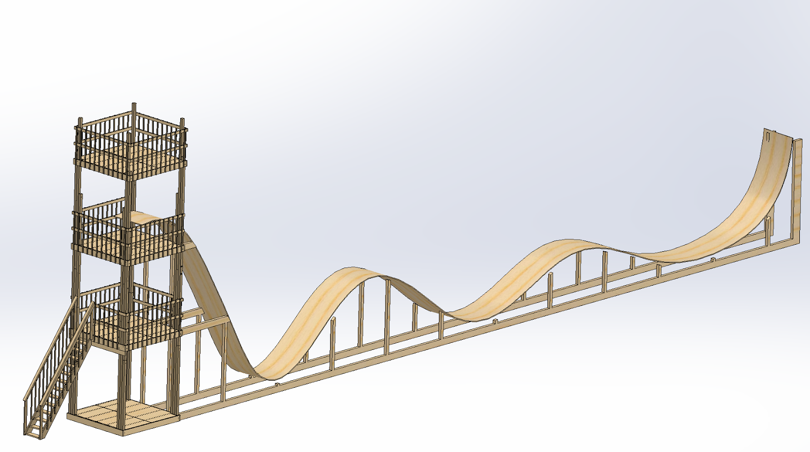
 They needed some sort of updated pictures by the next day, so I quickly came up with a rough version of the new (and final) track shape, and threw it into a Solidworks model with the same rough tower design as the previous designs.


Once we had a vague "We will probably let you build this if a professional engineer approves it" from MIT, we started designing for real, down to the 2x4.

Behind general structural integrity, the strongest force directing the design was Design for Assembly.  We would have a week to build the entire structure, and the labor skill of the students and incoming freshmen who would be doing much of the construction would range from extremely competent to which direction does the drill point?.  So the entire giant assembly would have to be fairly tolerant of sub-optimal construction quality, and possible to build rapidly, with only two people (Wesley and myself) overseeing most of the construction.

Everywhere possible, the frame of the roller coaster uses stock lumber lengths (mostly 8')  As I found out from building the climbing wall (which had almost no uncut pieces of lumber), processing all the lumber with chop saws is a big time sink.  

The frame supporting the track is made up of about 20 frames of varying height, but similar construction.  These frames could all be built on the ground independently of each other, and then assembled one-by-one once they were finished.

The track would be supported by about 100 2" long segments that interpolated the curve of the track.  These track sections could be fabricated in an assembly line-type system using chop saw jigs and assembly jigs.


As you can see from the above rendering, the roller coaster's frame also had built-in work platforms, so the track could be assembled without ladders or scaffolding.  In the final construction these platforms had railings which were not shown in the rendering.

The actual track surface was designed to be bent from three overlapping layers of 3/8" thick plywood.  The layers of plywood are easy to bend one at a time, but when three layers are sandwiched together the resulting surface is very stiff.  The plywood overhangs the frame supporting it by 6" on each side.  The cart that rolls down the roller coaster had wheels underneath the overhang, to make it impossible for the cart to fly off the track.

With the design as pictured below, I went to the Cambridge building commissioner to let him look at the plans.  He was pretty un-phased by the roller coaster, and gave feedback like make sure your railings are at least 42" tall and your stairs need to have 7" of rise and 11" of run per step.  


With those changes made, we had to find a structural engineering firm to sign of on our designs, in order for both MIT and Cambridge to okay the plans for construction.  Before sending the plans to a professional engineer, we did some 2.001-level analysis on the critical parts of the structure - the joists and spandrels supporting the floors, the tower posts, the track structure beneath the high-load areas, and the track surface itself.  

Eventually a local structural engineering firm (started by some MIT alums) willing to look at our plans for free was found.  They gave us a bunch of feedback about our design and structural calculations.  Most of our design choices checked out with them, although there were a few features they asked us to add, like diagonal bracing on some parts of the frame.  They went through our calculations thoroughly as well, and pointed out some spots where we could have made different or better assumptions about the loading of the structure.

They also asked us to make some kind of absurd changes to the roller coaster's tower.  In the original design, we spec'ed 5/8" bolts to hold the spandrels supporting each floor to the posts of the tower.  Citing some wood-loading vs bolt size chart, they asked us to make all our spandrel-supporting bolts 1" in diameter.  Early East Campus wooden structures used 1/2" threaded rod as bolts.  My freshman year, they used 5/8" bolts.  The year after that, the (different) structural engineering firm that review their design asked them to use 3/4" bolts on the fort.  This year: 1".  At this rate, there won't be any wood left in the structures in a few years.  

Here's a look at the structure supporting a floor f the roller coaster tower:


The diagonal braces on the tower also had to be significantly beefed-up.  In the past, these have consisted of sketchily screwed in chunks of 2x4.  Now, they had to have 2 1" bolts at the post, and 4(!) 3/4" bolts at the spandrel. Seriously, why don't we just build this out of solid steel next year?


Despite my personal opinion that these changes were unnecessary and frankly absurd (in addition to costly: 1" bolts cost around $10 apiece), we didn't really have any choice but to make the changes.  After all, for the Cambridge and MIT to let us build this thing and have people ride it, we absolutely needed our plans to be signed off by a professional engineer.

It was worth it though when we got a letter to the Cambridge building commissioner, approving our structure:


Here's a pile of renderings because I felt like playing with PhotoView360 in SolidWorks:


Also some sneak-peaks of the actual roller coaster, as compared to renderings:


Photo credit: Rachel Davis
And finally, a shot of the roller coaster plus fort (designed by Lauren '16 and Amanda 15').  I was doubtful that we would be able to build all of this given our time and labor constraints, but somehow we did:


September 30, 2014

Roller Coaster Track Design

The East Campus Roller Coaster happened, and was a great success.  Here's some proof.  I didn't get too many pictures of the construction process, since I was busy with the construction itself, so as I wait for other people's photos to trickle in, here are the details on how the shape of the roller coaster's track was designed.

To start off though, a brief back story about the roller coaster tradition and how I ended up being one of the people in charge of this year's 'coaster.

As far as I can tell, the first EC roller coaster, dubbed "8.01: The Ride" was built in 2004 (making this the 10th anniversary coaster).  The last roller coaster, "The Reverse Cowgirl" was in 2010, and had to be taken down prematurely since they weren't permitted.  So since then, EC has avoided roller coasters.

I've been thinking about the roller coaster since rush last year.  Pretty early on I was joined by Jaguar and then Wesley, hall-mates and fellow Mech E. 16's.  During the fall and winter, we started thinking about general track shape and construction method, and as soon as EC's Rush Chairs were elected near the beginning of spring semester 2014, we started talking with them about getting a roller coaster approved.

This post will cover track design.  A construction post will come later.

Let's get started.

Track designing started out like this:


Slightly fleshed out:


Yeah.

So we wanted a loop.

Loops are hard for lots of reason.  First, designing a loop that doesn't exert excessive g-forces at any point is non-trivial.  From a structure design construction standpoint, it's challenging as well, especially given the materials and labor limitations of Rush.   And convincing MIT administration, the city of Cambridge, and some professional structural engineers that our loop would be safe is an even harder problem.

The first of those problems was the easiest to deal with.

Fun Fact:  going into this project, I had never ridden a roller coaster, and didn't have the faintest idea how roller coaster loops were designed, other than that they weren't just circular.  I did a lot of reading about roller coaster loops, and some of the math behind them.

Before looking at any specific loop shapes though, I needed a way to look at the acceleration experienced by a person riding the roller coaster.  More specifically, I cared about the normal force between the roller coaster track and cart at any given point.  This number is important for both the riding sensation as well as design and analysis of the roller coaster structure.

Here's a simple mechanics view of the roller coaster with the cart at three different locations on the track.  I only cared about the forces normal to the track, and didn't particularly care about forces and accelerations in the direction of the track at this point.


The negative sign if inverted above comes from the fact that my code calculated theta using the arctangent of the slope.  Arctangent has a range from -Ï€/2 to Ï€/2, and therefore can't output an angle with a negative cosine.  Yes, atan2 could have fixed this.

I cranked out some MATLAB code which, given a set of points parametricly defining the shape of the track, could calculate the normal force (and G-forces) experienced at all points along the track.

Without going into the code line-by-line, here's how that works.  

First, I define the track as a set of points that looks something like [(x1,y1), (x2,y2), (x3,y3), ... (xn, yn)], where each x and y is a point along the track in meters with the origin on the ground at the start of the roller coaster.

To calculate the normal force, at any point you need the velocity, the radius of curvature of the track, and the angle of the track relative to horizontal.

Velocity at a given point is calculated using energy conservation with change in height from the starting point.  A friction factor is included in the velocity calculation to account for drag and track friction.

Angle at point is approximated by first calculating the slope from point n to point n+1 by (yn+1 - yn)/(xn+1 - xn).  Angle is just tan-1(slope).

Finally, the radius of curvature at any given point n is calculated by finding the circle circumscribing the triangle formed by points n-1, n, and n+1.

This is roughly illustrated in the image below, where the black dots represent the points along the track, the blue dotted line is the approximate slope at a point, and the red circle is the curvature at a point.


So, now that I had a way to analyze different track shapes,  I needed to come up with an exact shape for the roller coaster track.  I chose to use a clothoid loop (generated from part of an euler spiral).  The curvature of a clothoid loop gradually increases until the top of the loop, at which point it decreases again and transitions to flat.  Gradually increasing curvature means no huge spikes in G's experienced by the rider.  

Here's a simulation of a 45 degree slope followed by a loop:

Loop Shaping in MATLAB.  How 'bout that phase margin?  Oh, wait....

And a 60 degree slope, with friction included this time:

At the bottom of the slope, G's actually go to infinity because of the instantaneous change in slope. 
 As shown, I was able to create reasonably sized loops with reasonable G-forces.

That's pretty cool.  Unfortunately, we had to scrap the loop.  One of the steps to getting the 'coaster approved by MIT and Cambridge was going through MIT's Environment, Health and Safety department (EHS).  Basically, EHS said No Upside-Down People.  Period.

We had very little time to come up with a new track design, so we threw around some ideas including things liked banked curves, but decided on a (relatively) simple straight, multi-humped track design.  More specifically, it's an exponentially decaying cosine function plus an additional exponential decay, with a turn up at the end.  Even more explicitly, the track is the function 2.124e-.055xcos(.7x - .3) + 4.676e-.055x

Here's what that looks like in the G-force simulation:


Not too bad.  ~4.5 G's is pretty high though.  I traced the track curve into a Solidworks sketch as a spline, and then rounded out the curve at the bottom of the first hill to reduce the acceleration there.  I then exported the sketch as a DXF.  I found a MATLAB script that could convert DXF files into a matrix of coordinates.  I used this to pass the modified track shape into my same simulation.  Unfortunately, the process of converting things into splines and DXFs made the curve much less smooth, so the resulting acceleration plot is a bit jagged.  But the peaks were indeed reduced:


If you look carefully, you'll see that, with the friction estimate I used, G-forces actually go just barely negative at the top of the second hill.  Negative G's mean the cart would actually lift off the track at this point.  This turned out to not be the case on the actual ride, unless we gave the cart a really big push at the top.

I planned on taking some measurements to see how accurate the simulation was, but I didn't get around to securing good test equipment in time.  I tried out using a smartphone accelerometer strapped to the cart, but the resulting measurements were an incomprehensible pile of noise.

There's the abridged version of how we came up with the shape of the roller coaster.  Next in the series:  Roller coaster mechanical design, and maybe a glimpse into the whole approval process for this project.