Showing posts with label Shop. Show all posts

November 25, 2022

Lathe DRO Installation

I installed a DRO on the Clausing.  I got Aikron scales and console - the LCD console, a 1 micron slim magnetic scale for the cross slide, and 5 micron standard width scale for the carriage.  So far I'm very happy with it - the user interface is better than some US-made, much more expensive DRO's I've used, and being able to store a library of tool offsets is a real game changer - all the lathes I've used until now have been communal (and thoroughly abused...), so even though some of them had DRO's none of them had proper tool libraries.  Tool libraries make turning so much more efficient, and for tolerances over 50um or so I don't even need to measure anything. 


Mocking up the cross slide scale and read head placement - In order to not loose any travel, I had to get a scale that was slightly longer than the cross slide.  To get the the scale mounting fasteners to overlap, I had to make a longer cover on the back side of the cross slide.

The chuck-side scale mounting is a little unusual - this video from Robin Renzetti was the inspiration for that - as he points out,  if the scale is directly under the tip of the tool, machine inaccuracies like curvature in the travel of the cross slide don't cause diameter error between the scale measurement and where the tool actually is.  And these magnetic scales are small enough that chuck interference isn't an issue.


The original cover was a casting, but was almost the same profile as some off the shelf steel u-channel, so that's what I used for the new cover:


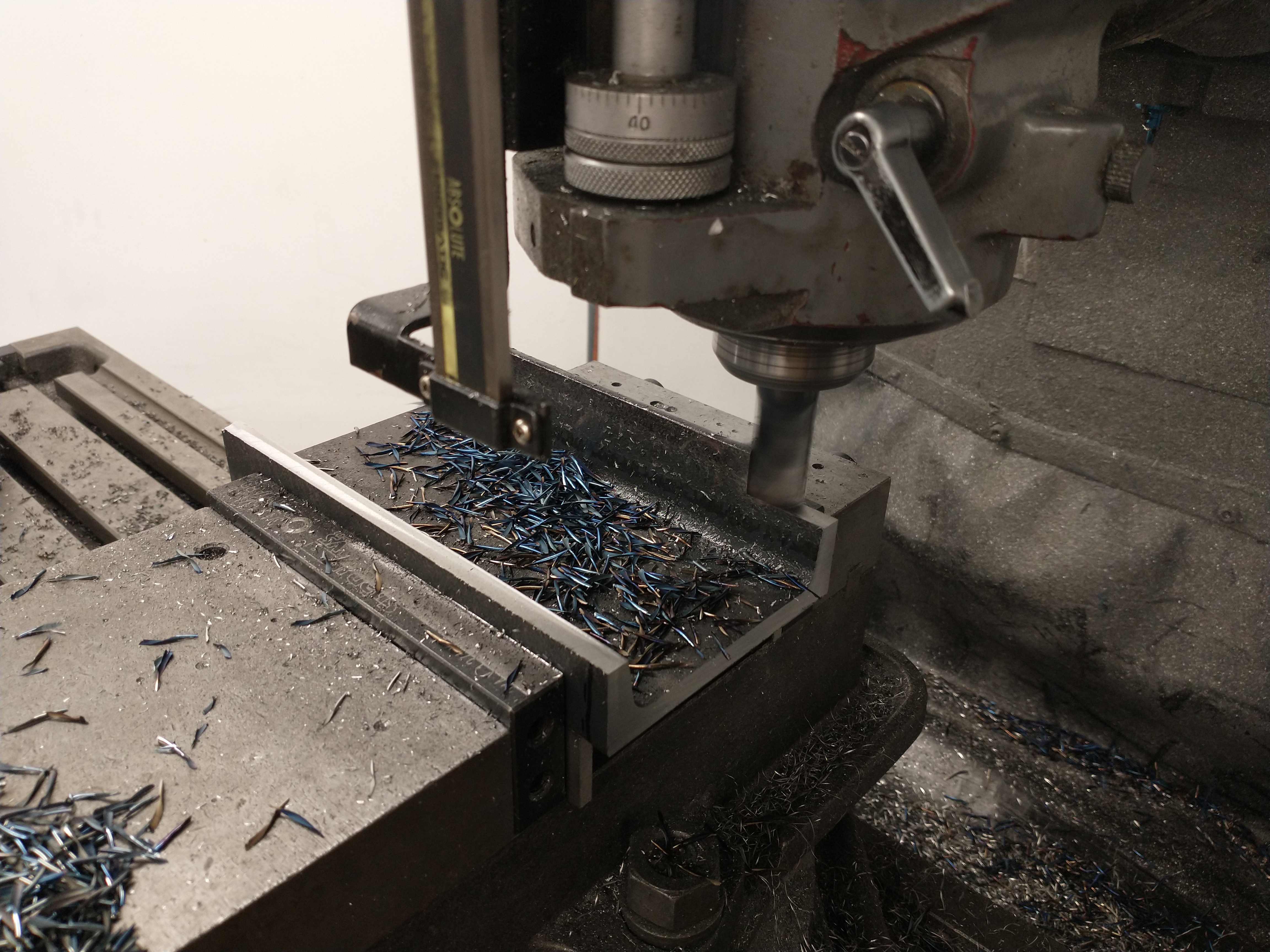
The extrusion was too big for my tiny mill so I used a Bridgeport at work:


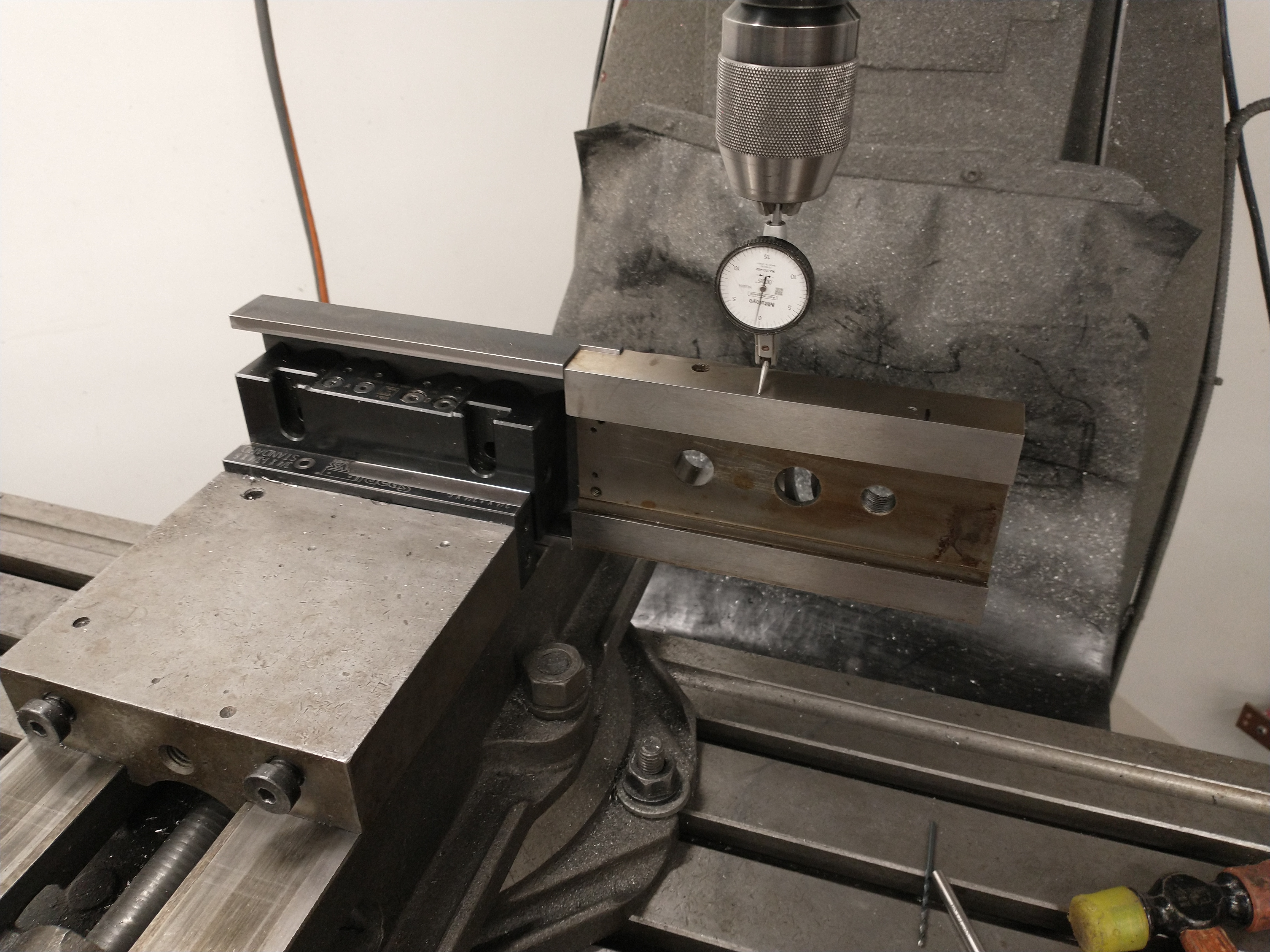
I fastened the u-channel to the cross slide and indicated the faces of the cross slide in for final machining to ensure the faces (especially the scale mounting face) were flush and parallel to the cross slide:


Before un-bolting the cover from the cross slide, I match-drilled a couple dowel pin holes and fixed them into the cross slide casting with retaining compound.  If I have to disassemble the cross slide at some point, it'll go back together repeatably.

Checking that the scale aligns with the cross slide travel - I did the vertical alignment by loosely tightening the mounting fasteners at each end and just tapping the the scale into alignment:

Thanks to the match-machining I did on the cross slide cover, I didn't have to do any shimming to get the z-alignment of the scale right:

Scale and read head both mounted:

I made a scale cover by gluing a neoprene rubber sheet to the cross slide with some Loctite 380.  Eventually I want to make a proper guard for the scale and proper way covers, but this does the job for now:

Mocking up the position of the carriage scale and read head on the back side of the machine:

To get the scale parallel to the lathe bed vertically, I sandwiched some bearings between a ground surface on the underside of the bed and the top of the scale:

Double checking the alignment with an indicator after mounting, but no adjustment required on this axis.  It took a few shims between the bed casting and scale in the other direction:

The read head was mounted with the stock hardware that came with the DRO, with a few modifications:


A couple p-clips hold down the cables and route them in a manageable direction:


The console was mounted to the power switch enclosure with a scrap piece of aluminum u-channel:


And here it is all set up:

April 19, 2022

Clausing 4901 Moving and Restoration

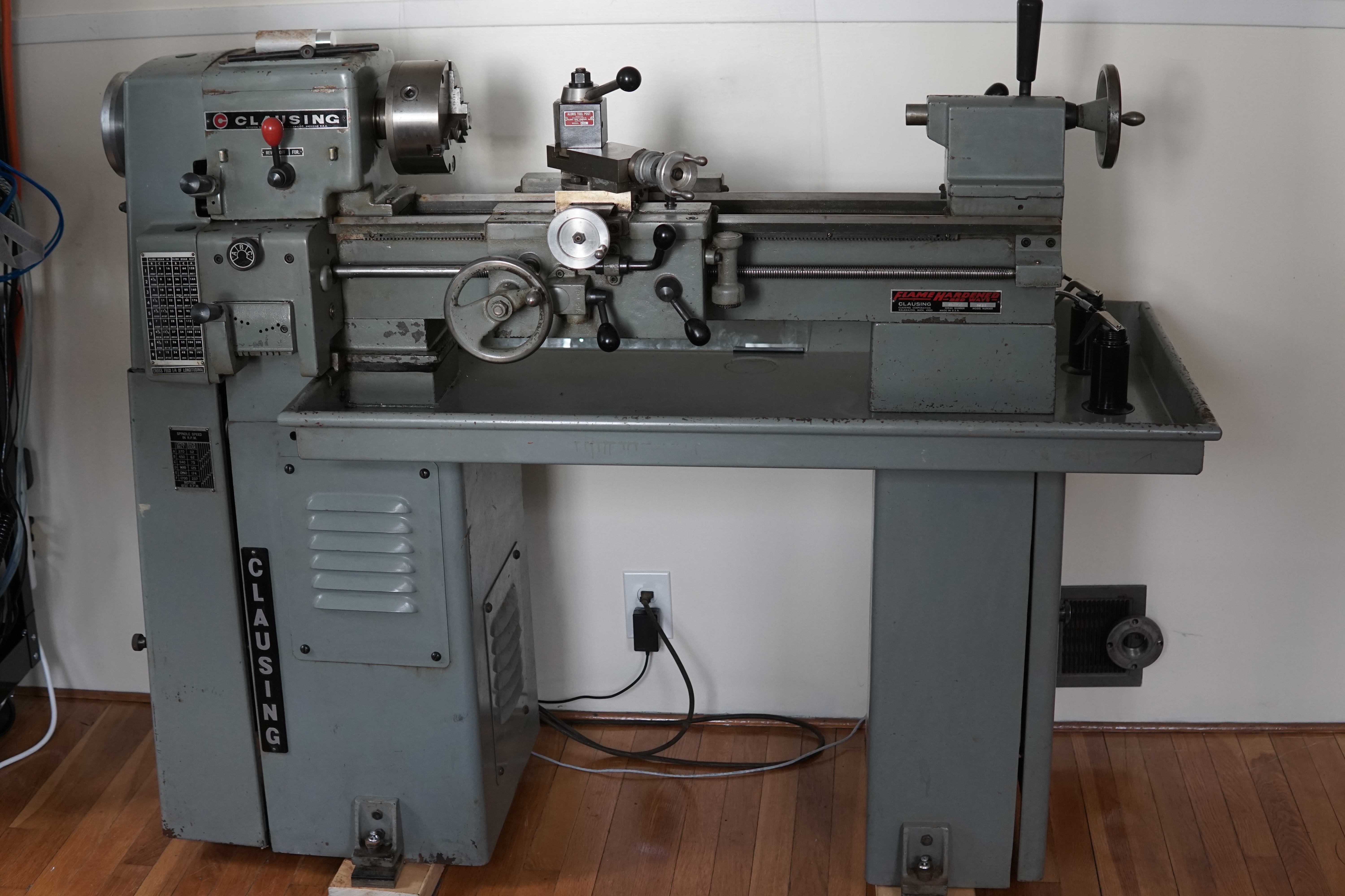
 I've been keeping my eye out on craiglist and machinery auctions for a small (but not that small) lathe for a while now, but small lathes (other than import mini-lathes) are pretty uncommon.  Someone Austin knows just bought a house just a few miles away from me with this Clausing 4900-series lathe in the basement, so we visited to take a look:


The scale of this lathe really didn't come across in photographs - it's way smaller than I originally thought from the pictures.  MITERS has a Clausing lathe of the same era, a 6918, which looks almost exactly the same but scaled up around 50% in every direction - from the original pictures I saw, I was expecting something more like the MITERS-lathe. 

I took some measurements, determined it would be possible to fit in my apartment, checked out the joist situation supporting the floor where the lathe would sit, and decided to go for it.  

For for the move, I recruited Rob and Andrew, who have moved many tons of machine tools over the last several years (probably all of which are much heavier than the 800-ish pounds this lathe is), plus Austin, Aaron, and myself.

We started by splitting the lathe off its base, to make it less top-heavy.  The lathe and chip tray were un-screwed from the two legs and lifted up with an engine hoist.  We removed the legs and slid Rob's heavy-duty dolly underneath.  


The basement the lathe was in had a door directly outside (so we didn't have to go up any stairs), but the door was pretty far from where we could get a pickup truck.  A dumpster blocked most of the driveway, so we had to haul the lathe up a small hill and around the dumpster.  The dolly rolled surprisingly well over the dirt and grass, even with ~600 lbs on it:


Lifted up again, dolly and all, ready for the truck to be backed under it:


Loaded up and strapped down in the Sliski-mobile.  The 8' truck bed makes the lathe look even smaller:


Getting the lathe into my place was a little tricky since there wasn't a lot of space to maneuver, but it went smoothly.

Here we are going through the front door.  We hand-lifted the lathe up the two steps.  A couple feet inside the front door there was an area of floor we had to avoid, where there's a trapdoor to our water heater.  There aren't joists spanning that section of floor, so we skirted around it.


The dolly just barely fit through the internal doorways, once the doors were removed from the hinges:


To re-assemble the lathe, we again lifted it with the engine hoist and re-attached the legs while the hoist was supporting the weight.  I put a couple 2x6's under the lathe's leveling feet, with big felt pads underneath, to spread the load and protect the floor.


The lathe back on it's stand, in all it's grungy glory:


Initially the headstock was full of paper and cloth scraps - some mice had made a home there.  Fortunately the mice were long gone, and thankfully hadn't left behind any mummified remains.  After vacuuming out all the detritus, here's what the inside of the headstock looked like:


The gears looked pretty rusty, the lever for engaging the back gear was stuck, and the spindle wouldn't turn once the power feed was engaged.  I worked things free by liberally spraying all the gears and shafts down with WD40 and gradually working the spindle back and forth by hand with the power feed gears engaged.  Eventually all the sticky spots in the gearing smoothed out, and the power feed and back gear shifted smoothly:


At first I thought I'd have to take the headstock apart to clean the rust off the gearing, but I was able to do it in-place with a small wire brush.  The state of the gears in the headstock also made me worried about the spindle bearings.  I oiled the spindle bearings and ran the spindle, and the oil that leaked out from the spindle was clean - so I'm assuming the spindle bearings aren't full of rust.

Scrubbed feed gears:


Scrubbed headstock gears:


Gears cleaned, power feed gears greased with some molybdenum disulphide grease, and a fresh timing belt installed - the original was damaged trying to remove it during the move.


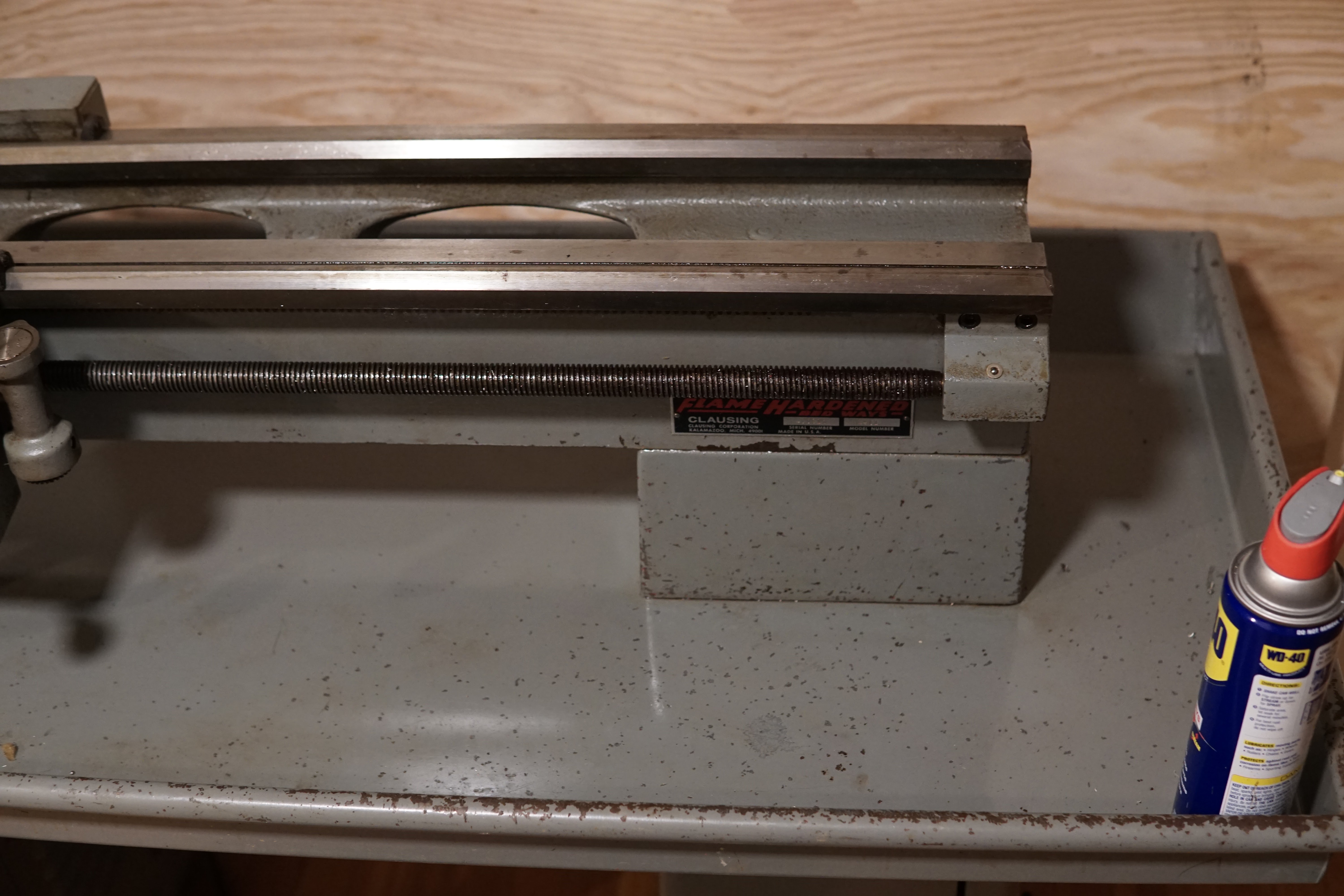
I cleaned the decades of gunk off the painted surfaces by spraying them down with WD40, scrubbing with a plastic-bristled brush, and wiping away the sludge.

Here's the chip pan mid-scrubbing:


Hard to believe this was hiding underneath all the dirt and oil:


I took the cross slide off, and the sliding surfaces look like they're in great condition.  The original grinding marks are still visible across the whole underside of the cross slide, and the lead screw nut has very little backlash.  Also encouraging, the cross slide doesn't tighten up at the extremes of its travel, which would have been a symptom of worn ways.


Here it is all scrubbed with the covers back on.  Looking pretty good, I think:


The lathe came with some great accessories, including the change gears for metric threading.  Most of the accessories had surface rust, but cleaned up really well with some Evaporust.

Before:


After:


8" 4-jaw chuck post-cleaning:


The lathe also came with the original paper manual, factory inspection report, and accessory manuals:


The manual is full of beautiful hand-drawn exploded view like these:


There were some other good bits of history in the manual.  The metric threading gears apparently cost $150 in ~1970 (~$1000 in today's dollars).  Unfortunately the micro carriage stop listed isn't around any more.


Eventually I'll get the manual properly scanned and post it online.  I was able to find the operator manual online already, but not the exploded views, parts lists, and accessory manuals, so someone else might find those useful.

Here it is running and taking it's first cuts out of some scrap aluminum:


The lathe is fully operational now, but I am planning on a few immediate upgrades like adding a digital readout.  All the lathes I've used have been communal (and most of them haven't even had a DRO).  I'm excited for the opportunity to set up a proper tool library with tool offsets stored on the DRO, and no one but me to mess them up.  That should make work way more efficient.  Along with the DRO I'll likely make a solid tool post mount to replace the compound slide, a-la-Renzetti.

The 3/4 HP single-phase AC motor and v-belt system might get swapped for something a little more powerful eventually (should be able to get around 3X the power out of a typical outlet), and electronic speed control would be a big improvement over shifting v-belts around.

October 6, 2020

Benchtop 5-Axis Mill

This was inevitable, but the pandemic has accelerated my home-shop setup.  What with leaving the lab almost a year ago (I miss you Lab Haas) and no MITERS for the foreseeable future, I haven't had access to any machine tools other than the tiny lathe for a while.  Time to fix that.

I've been following Pocket NC since 2012, after seeing them at the NY Maker Faire - they make a tiny but surprisingly capable 5-axis CNC mill.  It has basically the same layout as the big GROB machines, with a horizontal milling spindle moving in Z and X, and a cantilevered trunnion on the Y axis.   I was tempted to get one of their machines, but I think they're just too small and underpowered (and pretty expensive) for the sort of parts I make.  In my search for a small-enough-to-carry-upstairs-into-my-living-room-but-not-too-small CNC mill, I ran across a scaled-up Pocket NC clone made by a Chinese company, Xinshan Tech.  I couldn't find any examples of real people outside of China owning the machine, but after some emails back and forth with the company, including a bunch of videos, I was convinced that the machine was real and not a scam.  This machine was appealing, since it's a fair bit bigger than the Pocket NC, with ~50% more travel in each axis, all steel, servo (rather than stepper) driven, and much heavier (~70 kg).  I've gotten along just fine with 3-axis machines up until now, but I couldn't actually find any 3-axis mills that fit what I was looking for any better, and 5-axis opens up some interesting opportunities.

I decided to go for it, and a month later DHL showed up with a heavy crate:


Out of the crate and on the bench.  The machine is deceptively heavy given how small it looks, and is very awkward to hold onto.  Rigol scope in the background for scale.  


Back side of the spindle visible:  It's a generic 800W ER-11 water cooled spindles.  Maybe something to upgrade in the future:


The three linear axes are driven by brushless servos with integrated controllers:


A peek under the bellows way covers at the (allegedly Hiwin) X-axis ballscrew and one of the linear guides:


The linear axis ballscrews are coupled to the servos with disc couplings, which is nice to see


The backside of the machine, where you can see the X,Y, and A axis servos.  The rotary axes are driven with harmonic drive reductions and supported by crossed roller bearings, which I'm surprised was possible given the cost.


When I unpacked the electronics box, a few screws had worked loose in shipping and were rattling around.  The inside of the electronics box was not confidence-inspiring.  There's a generic 36V DC supply to run the servos, a 1.5 kW VFD, and some pretty sketchy wiring.   The machine seems good mechanically, so I'm letting this slide for now....


I've been using the shipping crate it came in as an enclosure.  If I fold the door up it keeps the chips in and the noise down a little, at the cost of seeing what's going on.  Eventually I'll build a proper enclosure.  I set the crate on top of a Harbor Freight rolling tool cart, which stores the power supply box, water cooling, and related tools:


Screenshot of the the control software below.  The software isn't anything fancy, but does the job.  There are amusingly mis-translated buttons like "Knife", which actually runs the tool probing macro, "overrate", which is the feed override, and "Cold Fog", which presumably would turn on mist coolant if the machine had it.


Not particularly exciting, but here was my first working attempt at a multi-axis toolpath (video at 16x):


Here's one of the first "real" parts I've made - the front side of a motor housing.  Most of the material removal was done with a Datron 3mm single-flute end mill.  Thanks to the rotary table I could do this part in one setup, rather than machining one side, machining a fixture, and machining the other side like I would on a 3-axis machine.  Video at 8x speed.

Here's pretending the mill is a lathe and machining a shaft for said motor, including a lock ring thread cut with a 60 degree chamfer mill.  HSMWorks, which I've been using for CAM since the beginning, is pretty terrible for this style of toolpath, so the surface finish is a little weird.  It buffed out easily though.  In this picture the part is done and being parted off:


And here's that half-a-motor-housing and shaft with a rotor for a frameless motor installed (held on by a threaded lockring also made on the mill), and bearings and commutation encoder magnet pressed in.  


I haven't pushed the machine too hard yet, in the interest of keeping noise down.  It's in my 2nd floor living room, and not very well enclosed, so I've been making the toolpaths conservative to avoid complaints from my neighbors.

Amusing setup from today - a part in the tiny lathe 3-jaw chuck, held in an ER-40 collet chuck, bolted to the table.  Milling a circular dovetail in the part (which is a fixture for yet another part), to match the dovetails milled into the lathe chuck soft jaws:  No dovetail cutter required.


Summary of thoughts/impressions so far:
  • The core mechanical pieces of the machine seem pretty good.  Brushless servos, linear guides, ballscrews, and harmonic drives, on a steel structure is impressive at this price point.
  • The less-critical hardware is a little janky - the bellows way covers, the sheet metal spindle cover, the electronics box, the water cooling loop.  But those are all relatively straightforward to re-do or repair if needed.
  • With good tools (I've been having great luck with Datron single flute cutters for roughing), it performs pretty well cutting aluminum.  I've been roughing with a 3mm endmill at 20k RPM, 2.5mm stepover, .5mm stepdown, and 2000mm/min feed with no problem.  It could definitely be pushed harder but it gets loud.  I haven't tried harder materials yet.
  • I haven't done a ton of experimenting yet, but "conventional" style toolpaths with large stepover and small stepdown seem to perform better than "adaptive" or "trochoidal" style toolpaths with a large stepdown and small stepover.  Needs more testing though.
  • I wish I had a way to pre-set tool lengths with the ER-11 spindle.  The machine has a built-in tool probe, but swapping collets and probing takes a while.  I'm thinking about making a bunch of shrink-fit holders that all have the same shank diameter and bottom out in the spindle, so the collet and collet nut never have to come all the way off. 
  • There are a few vendors of the machine (It's even on Amazon, but also RobotDigg and a few other sites), but it's cheaper to get directly from Xinshan.  
  • Support has been really excellent so far.  I've had tons of questions about how things work, and I always get a response the next day.  When I've had g-code that behaves confusingly, they'll run the code on their machine and send me a video.
  • CAM-wise, I've been using HSMWorks.  I think the kids these days are using Fusion 360 (Autodesk bought HSMWorks and I think has ported it into Fusion), but I've never tried it.  Solidworks integration is super nice since your CAM updates when your model updates, and I don't really want to switch to Fusion for CAD.  HSMWorks/Fusion 4/5-axis toolpaths are kind of a joke, but 3+2 (position the rotary axes then do a 3-axis toolpath) work great.  The "real" answer for good 5-axis toolpaths is probably a more legit stand-alone CAM software, but I'm going to stick to HSMWorks for everything I can.  
  • Cool feature, the machine can do TCP, Tool Point Center control - this means that the CAM origin does not need to be at the machine origin (the intersection of the two rotary axes).  You can put the CAM origin wherever, set the work coordinate system offsets by touching off to the part, and the machine will figure out the kinematics.  This makes CAM much simpler, since you don't have to know where the part/stock are on the machine when you're doing the CAM.  That's what you'd expect for 3-axis stuff, but with the two rotary axes, it's not just an offset in X, Y and Z anymore.  I haven't been to adventurous with this, but offsetting the Z at least seem to work just fine.