

Planar magnetic (a.k.a. "orthodynamic", "isodynamic", etc) drivers are a pretty neat topology of linear motor, which, as far as I can tell, has found no application besides speakers and headphones. Here's a well-diagrammed explanation of how they work.
Instead of a voicecoil actuator which drives a stiff cone back and forth, like a conventional speaker driver, a thin membrane with conductive traces sandwiched within a funny magnet arrangement moves back and forth.
 |
| image credit: innerfidelity.com |
I started out by playing with magnet arrangements in FEMM, to see how sensitive this arrangement was to changes in magnet dimensions and spacing, and I ended up here:
This uses 1/8" square N52 magnets, with a 2mm airgap, and 9mm pitch. The array 2 inches long (into the page), and each bar is a pair of 1/8" x 1/8" x 1" magnets, which are cheaply available on ebay:

Here's the tangential flux density (which is the normal force producing component) in the middle of the air gap:

Doubling the depth of the magnets got it up to .5T peak (the path around the magnet gets longer, so less flux leaks through it), but I decided it wasn't worth the more than double magnet cost (they are harder to find magnetized through the small face).
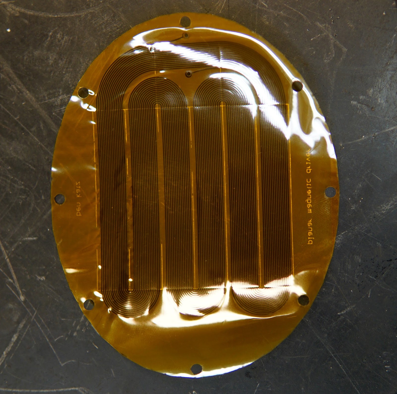
Here's what the actual flex pcb coil looks like. The traces go up and down in the regions of ±.35T field in the plot above. This was very unpleasant to draw in Eagle. 0.25mm trace width with .5mm pitch. PCBWay claims to be able to do .1mm between traces, but I didn't want to push it.

For the actual PCB, I chose single layer, 75µm flexible adhesiveless base, .1mm FPC thickness, no solder mask, and 1/3 oz copper, to keep the board as light and flexible as possible. Maybe a 2-sided trace would have been better, for a higher ratio of conductor to pcb material, but this whole thing is an experiment anyway.

Front: A few of them came out a little wrinkly. Not sure why, or if it will cause problems. In retrospect, it might have been a good idea to put a thick copper trace around the outside of the whole board, to stiffen up the perimeter. Coil resistance came out to 16 ohms.

Back:
I CNC milled half of a housing out of some Delrin:


Glued in the magnets:

There's a lip on the housing that will apply some tension to the flex pcb to hold it flat, once both halves of the housing are made, but it was secure enough for some testing with only one half.


It actually works even with only half of the magnet arrangement - half the magnet gets you half the flux density. It should produce the same volume on roughly half the power, once the whole thing is assembled.


I'll reserve qualitative judgement until the whole thing is assembled, but from the brief testing I've done on this single partially assembled driver, it seems promising.
Nice projekt! Love your approach to building the diaphragma. Never seen that... To get a better sound you can change the flex PCB to a lighter version.
ReplyDeleteVery nice project, how did you decide what materials to use for the diaphragm?
ReplyDelete