

This is a relatively quick little project, but one that's been on my mind for more than a year now, and finally got around to building.
Inverted pendulums can be a pretty cool testbed for controls stuff. They're relatively simple, but very non-linear systems, and there are a lot of approaches to swinging up and stabilizing the pendulum. The Furuta pendulum style of machine is particularly interesting, I think. If built right, they can be very small but have unlimited travel, unlike the car-pole style of inverted pendulum, which eventually runs out of track for the cart. Although the full non-linear equations of motion are much more gnarly, for small motions the behavior is largely the same, so it's not actually any harder to stabilize.
This post will cover all the mechanical stuff, and the next one will go through the controls I've done.
Here's a video of it running, so you don't have to scroll through the whole post to find the only part you actually care about:
Like all good projects, this one starts with a motor. A familiar motor. I re-used the Turnigy 5208 gimbal motor I characterized a while back. I spent a while thinking about what kind of motor I wanted to use for this project - I wanted low friction, no backlash (direct drive), and low torque ripple, to make control as pleasant as possible. A direct-drive brushed servodisc would have worked great, except that I really wanted a motor with a hole through the center of the shaft. This way I could pass the wires to the pendulum encoder through a slip ring, and get infinite rotation out of the top half of the pendulum. Since I already had this gimbal motor on hand, I made some serious modifications to it to give it a hollow shaft and to kill its cogging torque.

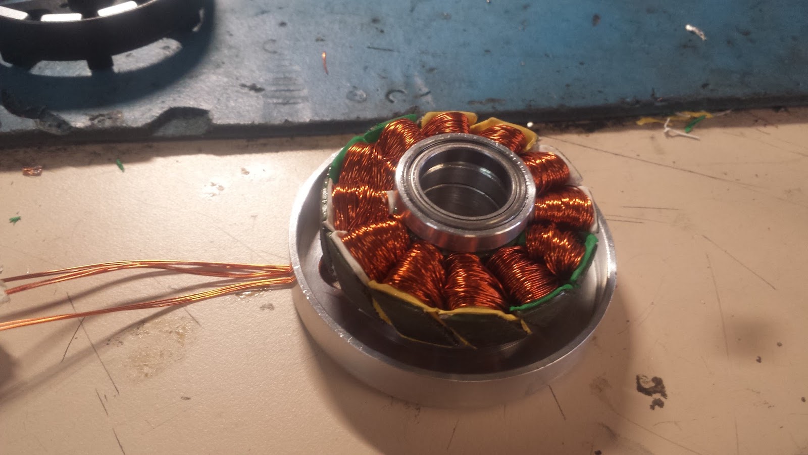
First step was pull off al the windings. It needed rewinding anyway, since it was wound much colder than I wanted for 12V operation. Then I split the laminations apart with a razor blade, re-flattened them in a vice, and glued them back together with a skew. Skewing the stator like this almost completely kills the cogging torque (the closer you get to a full pitch of skew, the lower the cogging), at the cost of lowering your motor constant.

Here it is rewound, with 20 turns/tooth of 4 parallel strands of 22 AWG wire. Stock the motor had 150 turns/tooth.

Machined a new housing for the stator, with extra-large thin section rotor bearings to fit a hollow shaft with a 12mm bore.
I forgot to take pictures of the rotor, but I basically just machined a new aluminum can, pressed the original rotor into it, and then machined away everything but the magnets and can from the original motor. Here's the basic motor + encoder assembly. The optical encoder was the only one I could find with a large enough disc to fit the hollow shaft, so it defined the shape of the pendulum assembly. I still had to machine a new hub for the disc though.

Motor cross section (minus windings and magnet, showing how the shaft and bearings work out:

Here's the pendulum assembly that sits on top of the rotor. The pendulum attaches to a spindle with a magnet stuck to the opposite end of the shaft. An Allegro A1335 chip on a CNC-routed pcb outputs the angle of the magnet over SPI, which is passed through a slip ring back to the motor controller.

A big optical encoder is mounted to the bottom of the the motor, and is used for both motor commutation and pendulum control. One of my little motor drivers mounts to the encoder housing. I had to jumper an extra header to it to wire in power for the encoder.

Here's the unfinished version, with the pendulum stabilized. I didn't have all the right pieces of plastic on hand to machine the housings from, so I started work on the control stuff with some 3D-printed housings to keep everything together.

I machined plastic housings out of some chunks of delrin, and turned a circular aluminum base. Here's my favourite technique for making big circular plates: Bandsaw out the rough shape, drill a hole through the center, use a big bolt as an arbor, and turn it round on a lathe:

Pretty pictures:


Lemo power connector goodness:

Stabilized upright:


Beautiful work. I share your love of Lemo connectors :) Got a randomly-acquired 16-pin set sitting in a drawer waiting for the right project...
ReplyDelete