

Here's the detailed post to go with the pictures and videos I've been dribbling out over the last few months.
Last episode the mechanism was mostly finished, and was just missing the guide rollers that constrain the screw to linear motion and react the motor torque on the screw.

The bump on the outside of the rollers was turned with a custom-made form tool. I machined the form tool on the CNC mill out of a piece of (allegedly) high speed steel. First I tried on a high speed steel lathe tool blank, but the small un-coated carbide endmill I tried with didn't last very long. I dug through my bin of lathe blanks and broken end mill shanks, and tested the hardness of a bunch of pieces against the lathe blank that foiled my first attempt. I found the shank of an old Harbor Freight HSS end mill, which was (perhaps unsurprisingly) appreciably softer than all the other pieces of HSS I had lying around. But the rollers are plastic, and I was making ~10 of them, not 1000's, so it was still hard enough.
I prepared the endmill shank on one of the MITERS Bridgeports - milling the rounded sides flat, and cutting in a top rake and front clearance angle:

I stuck the tool in the CNC mill to cut the profile:

And here's a close-up of the final tool and one of the machined rollers:
.jpg)
.jpg)
.gif)
The axles for the rollers are undersized (h8 tolerance) dowel pins, which are a nice slip-fit into the bearing IDs. The fit between the dowels and the machined aluminum support piece is close enough that the pins can be pushed in and out by hand, but the friction is enough to keep them put for testing. They'll be permanently held in place by a drop of retaining compound on one side, which should still let me press the pins out if I need to.
.JPG)

With the rollers made, the mechanism was ready for testing under power. I was a little worried about commutation with the motor encoder offset through a 1:1 spur gear pair, but it worked fine. The first test was to apply a constant torque and make sure the mechanism felt smooth throughout its travel.
Things felt good, so next I put it into closed-loop position control and thrashed the leg back and forth. I didn't notice until I filmed this video that the regen during acceleration was boosting the output voltage of the power supply up to >40V. I was lucky the motor controller didn't get toasted.
During this testing I accidentally crashed the screw into the hardstop without a bumper - the cam followers ran into the end of the cam slots, so all the kinetic energy in the rotor went into shearing off the guide rollers. I remade all the rollers out of PEEK to give them a bit more strength. New PEEK one in black on the left, white delrin one with a chunk missing on the right:


For high power testing, I put together a simple test fixture for launching a steel puck the same weight as the final robot will be (hopefully). The classic way robot-folk do their first leg tests is on a vertical linear rail, but a multi-meter tall rail wouldn't be very practical. So instead of having the robot jump, it throws something of equivalent weight.
The screw mechanism mounts to a pair of machined plates and aluminum extrusions left over from the CNC mill enclosure. A cart rides the rails with the same type of v-groove wheels some 3d-printers use. The cart cradles a puck of stainless steel until it reaches the end of its travel, at which point the cart crashes to a stop and the steel puck is ejected.
Here's the test fixture, with electronics and batteries zip-tied to a piece of acrylic. The electronics are just a Nucleo and a CAN transceiver - the Nucleo talks to the motor drive over CAN, and to my laptop over USB:


The picture below shows the v-rollers and matching groove in the aluminum extrusions:

Rather than building some elaborate stand for the apparatus, I bolted on a couple wooden stakes and rammed the test setup into the ground:
.gif)

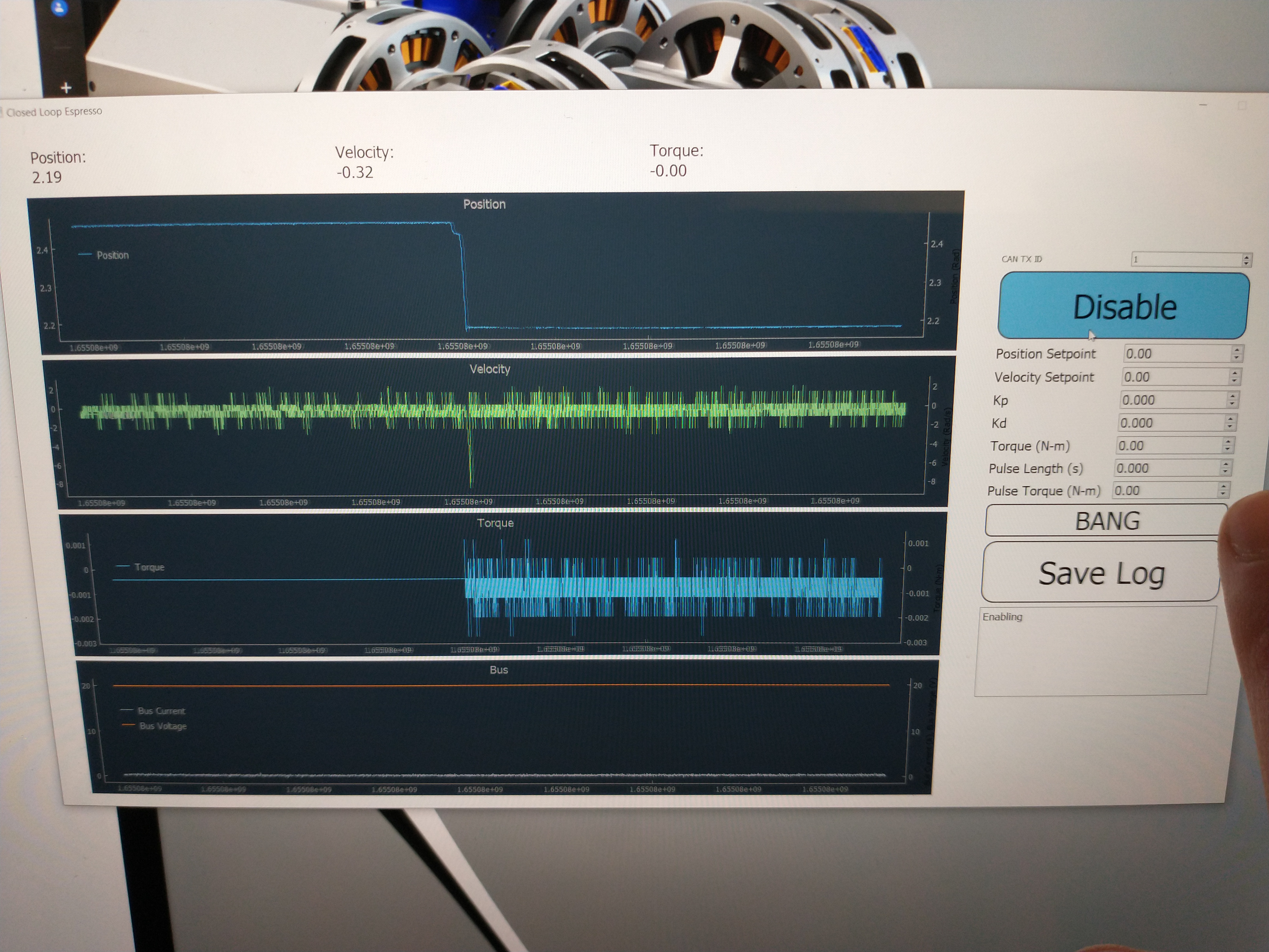
On the software side, I threw together a quick python GUI based off the espresso machine software. It lets me save logs, manually set gains and commands, and send short torque pulse commands with the "BANG" button:
The first couple times I set up outside I had mysterious electrical issues - sometimes, when the motor was enabled and switching, the USB communication to the laptop would drop out and not come back until the Nucleo was power cycled. Eventually I traced it back to the USB hub I had the Nucleo plugged in, but the issue was very intermittent and only showed up when the motor was powered with over 25V. Once I ditched the USB hub, everything worked reliably. Here's the first outdoor testing video:
This testing only got to about 3.3 meters, not the ~9 meters my original transmission ratio optimization predicted, but there were a few things going wrong.
One problem was pretty clear from the logs - once the motor gets up to about 7000 RPM, current tracking goes terribly wrong. I think this is from the overcurrent protection on the DRV8302 gate driver on the motor controller triggering and turning off the FETs briefly before re-enabling, but I don't (currently) log the faults, so I'm not sure yet.
The motor speed only reaches ~700 rad/s vs the 1200 it's supposed to reach, which checks out in terms of the final height the puck reached.

Another issue is that the motor isn't actually producing the torque I expect. I got these custom-wound from T-Motor and it seems like they were off a bit - the torque constant measures out to be about 30% lower than I expected. Sadly the motor in the mechanism right now is potted in, so I can't rewind it, or even remove it without some serious effort. I've already cranked up the motor drive peak current to 60A from the 40A I usually run, and I'd have to turn in up to ~80A to get the torque I was expecting, and I'm a bit hesitant to do that. But even with the torque constant being off, it should be able to launch a lot higher given the current control issues during most of the stroke.
Never trust T-Motor specs lol (we had lot of issues with the AK-10)
ReplyDeletethat was really great, thanks for sharing this
ReplyDeleteCrank it to 80A and send it. Yolo.
ReplyDeleteGreat post, thank you. Too bad about the T-Motor specs.
ReplyDelete