

This came out of thinking about sliding mode control and direct torque control, thanks to the nonlinear controls class I took this past term. I did a more formal writeup for my final paper for the class, in the (unlikely) case you find that a more readable format.
In a typical FOC implementation, phase currents are measured and transformed into the rotor frame to get d and q axis currents. Then two PI loops are run to control the d and q currents, with some feed-forward deal with the coupling between the voltage equations. The two PI controllers output d and q voltages, which are transformed back to the stator frame, and approximated with PWM.
This usually works great, but here's another controller I thought of which is (maybe) conceptually easier, and requires no controller design or gain calculating to work. In fact, it doesn't even use any motor parameters. And it doesn't even use PWM. At every step, it just picks which switches to turn on and off. Because of how it works, it's quite robust to changing parameters, like the motor's inductance changing when it saturates. Also, it has as fast as possible response given the open-loop dynamics of the motor.
The basic idea is as follows: Given the position of the rotor and errors in d and q currents, which switches should be turned on and off to make the error decrease as fast as possible?
Every loop cycle, the controller measures current, looks at the error and where the rotor is, and chooses the switch states that send the current error towards zero the fastest.
While it probably looks very confusing at first, I think the vector diagram below best explains the situation:

First, there are six vectors drawn in black, V1-V6, which represent the six stator voltage vectors. Each of these corresponds to a set of switch-states. The states with all switches on or all switches off are not used. Then there's the ĩ vector in blue, which is the vector sum of the d and q current errors. In red is the (negative of the) vector from motor dynamics, minus inductance. Looking at the motor voltage equations in d and q:
$$V_{d} = R_{d}i_{d} + L_{d}\frac{d i_{d}}{dt} - \omega L_{q}i_{q}$$
$$V_{q} = R_{q}i_{q} + L_{q}\frac{d i_{q}}{dt} + \omega(L_{d}i_{d} + \lambda_{r})$$
Vdynamics is equal to the vector sum of
$$ -R_{d}i_{d} + \omega L_{q}i_{q}$$
and
$$-R_{q}i_{q} - \omega(L_{d}i_{d} + \lambda_{r})$$
in the d and q directions, respectively.
If the d-axis component of stator voltage plus the d-axis component of the dynamics is positive, then id will increase, and the same for the q axis.
The green vectors are di/dt scaled by inductance - mostly their direction is what matters. Given a dynamics vector and one of the stator vectors, the six di/dt vectors are the possible directions the current will change in.
Basically:
$$V_{stator} + V_{dynamics} = L\frac{d i}{dt}$$
The intuition is, pick the stator voltage vector which causes the di/dt vector to be in the right direction. The "right" direction is the direction of the error vector, ĩ. In the 1-D case, if error is positive, that means that actual current is less than desired current, so di/dt should be positive to cause current to increase.
To pick the right set of switch states, just take the dot product of the error vector and the six stator vectors, and then pick the switch state corresponding to the largest dot product. But wait, that's not the right thing to do, is it? Shouldn't I be picking the switch state which causes the dot product of the di/dt vectors and error vector to be the largest? Yes, but fortunately these two decisions are actually the same. Vdynamics is added to all the stator vectors, and dot products distribute. So you can ignore the Vdynamics vector, and just pick based on the stator voltage vectors and the error vector.
To limit switching frequency, you can also add a "hysteresis circle" around the origin. As in, if the error vector lies within the circle, don't change switch states:
Does it actually work?
Well, my motor model says it does. This is also using a motor model which includes a lookup table for inductance and flux linkage saturation. The motor parameters are from a KIA hybrid starter generator at 160 volts, with switching frequency limited to 15 kHz. I also threw in some real hardware effects like a few amps of noise on the current sensors, and 12 μs of propagation delay (which occurs in the Toyota Prius inverter).
Here's what phase current looks like at ~20 phase amps. As expected, it has way more ripple than a linear controller would, since the minimum switch on-time is one loop period, but it's quite tolerable - especially given the 200A max current of this system.

"It works is simulation" is where most people would have stopped, especially for a class project, but what's the point of controls if you don't put it on hardware? And then ride your hardware:

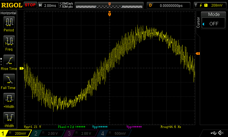
So how'd it work? Here's 20 phase amps on the actual motor, as measured by LEM-stick. Hey, that plot looks really familiar!
And here's a log from spinning up the wheels off the ground. d-axis current stops tracking around 1000 rad/s, because the reference currents were generated using an in correct inductance. So the commanded trajectory was actually un-trackable.

Qualitatively, it performed quite well. It produces an audible white-noise hiss from the extra current ripple. 1600 rad/s in the plot above corresponds to a ground speed of over 130 mph, although in reality on the ground the kart won't have the power (nor the space, in Cambridge at least) to go that fast. Yet.

This type of controller is often not feasible to implement - for small hobby motors, for example, the inductance is too low for this to work with reasonable loop frequencies. This is one reason PWM is great - the timing resolution of when the switches turn on and off is dictated by a super-fast timer that runs in the background, rather than by the timing of the control loop. So for a given loop rate, normal PWM-based approaches will have way less current ripple than this controller. But for some motors (in particular high-inductance motors like those in electric cars), the numbers actually work out fairly favorably, and you can get away with running this controller at reasonable speeds.
There are certainly some improvements that could be made to this by including motor parameters to reduce current ripple, but I haven't tried any of them out yet.
Also, I thought I was really cool and came up with something new here, but (unsurprisingly) it turns out other people have already done similar things. Although they don't put it on hardware.
Hey there,
ReplyDeleteI need a help for choosing a good controller
Can you suggest me any good quality controller? Please reply me with a great quality controller model, and where I can get it.
Thanks for the Great and informative article. thanks for sharing.
Levy.