February 4, 2013

OarCycle: Tacked Front Triangle

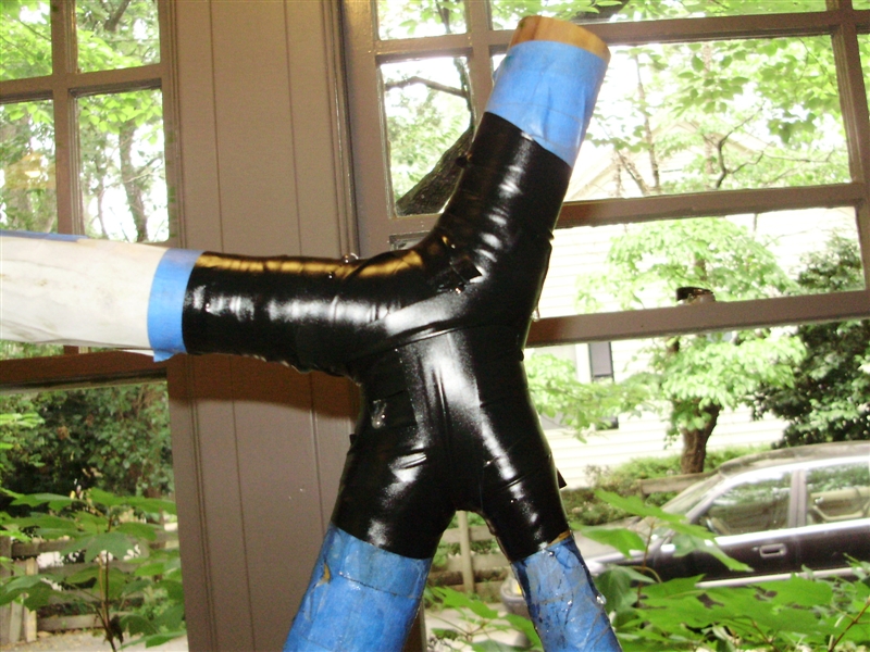
I finished mitering the carbon fiber tubes, and tacked the frame's front triangle together.  Before doing so, I put a layer of fiberglass composite over the outside of the bottom bracket shell and head tube.  I attempted to vacuum bag the tubes, but I forgot about all the volume on the inside of the tubes when making the vacuum bags.  When I turned on the vacuum pump, all the bagging was sucked into the centers of the tubes, which caused the bagging to leak.  To avoid having to run the pump constantly to maintain the vacuum while the epoxy cured, I went back to the electrical tape method of compressing the composite.


To fill some gaps due to imperfect mitering and to fillet the intersections of the tubes, I made some epoxy filler by shredding carbon fiber tow.  The resulting mixture was smoothed over all the joints:


Because Carbon Fiber, the frame is much lighter than it looks, with the front triangle weighing in at 720 grams.  For the complete frame, I am aiming for something just above 1 kg, making  this frame under half the weight of my bamboo frame.


I made dropouts track fork ends to hold the rear wheel out of scrap 1/4" aluminum plate.  The two dropouts were roughed out independently, and then clamped together for final machining.  The non-right-angles were done by some creative clamping on the mill.


I touched up the dropouts on the belt sander, to round off some sharp corners and make them shiny:

Who needs a waterjet cutter....


Next up:  the rear triangle.  This bit is going to take much longer, because a) IAP is over, and b) I am out of pre-made carbon fiber tube.  I plan on making some sort of form for the seat stays and chain stays out of foam, and laying up the tubes from carbon fiber cloth myself.

February 2, 2013

Bike Frame Jig

Begin Build Everything Before IAP Ends mode:

I chopped up the oar with an angle grinder.  Sorry MITERS.  

Almost looks like a real bicycle

Rather than deconstructing an old aluminum frame for the head tube, bottom bracket shell, and dropouts, I will be making my own.  I learned how to make threads on the lathe, and made my own BB shell out of some aluminum tubing.  It is much thinner than one you would find on an all-aluminum bike, but since it will be wrapped in a few layers of fiber-reinforced-epoxy-composites it should be fine.  All the aluminum parts of the frame will be coated first in a layer of fiberglass composite before any carbon fiber, to prevent galvanic corrosion.


The BB shell is left hand threaded on the right side and right hand threaded on the left side.


Unlike my bamboo bicycle build, this time around I do not have a donor bicycle I can use as a jig. I built my own jig using some 80-20 extrusion, nylon rod, and aluminum plate I could scavenge.  I turned the nylon rod into 5 cones.  These cones will fit into the ends of the frame's tubes, holding them precisely centered.


Here is the finished jig for the front half of the frame.  It is fairly adjustable, so I could use it to build other frames later on, if I wanted to (provided they are the same size or smaller, and the head tube angle is roughly the same as the seat tube angle).  


I have the jig set up to mimic the geometry of the 56cm Trek Madone 7, their highest end road bike.  From the bike geometry information they provided, I was able to CAD the entire bike's geometry, and figure out the shape fo the jig from there.


The cones can be positioned at any point along the 80-20 extrusion:


With the jig done, I started mitering the carbon fiber tubes.  I did this on the mill with a hole saw.  Weird angles were made by rotating the mill head:


One down, two more to go.


January 30, 2013

A Preview of Upcoming Projects

First, a flying thing.  Nick let me have his old quadrotor, including motors and ESCs.  It should be pretty straight forward to get running again, with a new battery, flight controller, and transmitter/receiver system.


This oar has apparently been sitting around MITERS for a few years.  The oar is made out of a slightly elliptical tapering carbon fiber tube.  I plan on chopping up the oar and turning it into a bicycle frame.  The joints will probably a combination of CF and fiberglass, depending on what I can find.  One of the goals for this project is to basically not spend any money on it  - if there some bike parts I can't find, I'm not going to worry about conforming bike-part standards, and just make my own components.


I already have most of a back wheel for the bike, and a pretty nice one at that.  It was missing an axle and bearings, but I was able to find replacements in a drawer of parts left over from the MITERS bike shop era.  


After I figure out a good bike geometry, I will build a proper frame jig to line up all the tubes for joining.  Since the oar tubing is too wide to use for the rear triangle (seat stays and chain stays), I will be using other materials.  My current idea is to do something like this for at least the chainstays, as there are a number of very thin carbon fiber tubes around MITERS.

January 24, 2013

Battery Building, Motor Woes, and a Rideable Tricycle

Here is an unfortunately large update, due to my blogging laziness.  

I spent way too much time inhaling soldering fumes while building two battery packs for the trike.  As you may notice the cells I ended up using were the green flavored variety (given to me by Dane), rather than the cardboard covered ones  I was planning on using.  The green cells are 2.5 Ah, as opposed to the 2.2 of the others, and have 2/3 the internal resistance.  

I started the packs by making Tetris-like blocks tacked together with hot glue, with cells soldered in parallel.


These blocks were then tacked to each other, and wired in series.  Below is the lower half of one of the packs.  The gap separating the three leftmost cells from the rest of the pack is for the drive shaft.


Each 12S3P pack is actually made from 2 6S3P packs connected in series.  I did this because no hobby chargers (that I know of) can balance charge a 12S pack, and the charger I have been using can only charge up to 6S packs.  Each half of the pack was packaged in "bottle armor" made from giant 3 liter soda bottles.  When heated, soda bottles shrink like heatshrink tubing, and form a hard plastic case when they cool.  The weird 3-cell extension off the pack could not be bottle-covered, so I used a combination of large heatshrink tubing and kapton tape.


For the power leads, I used XT60 connectors - one entire connector each for positive and negative.


To hide the pack, I made a cover out of matte black acrylic.  In the process, I found a really good way of making clean bends in acrylic.  I clamped thick aluminum blocks .25" above and below the bend line, and heated the gap with a heat gun.  The blocks both stop the acrylic outside of the bend area from heating up and prevent anything but the bend line from deforming.


The result:


To stop the battery from banging around, I coated the inside of the battery compartment with soft foam tape.


To make the seat actually able to support a person's weight, I coated over the plastic frame with fiberglass.  First, I covered the frame in electrical tape.  This made a surface for the cloth to rest on, and epoxy does not stick to electrical tape.


Due to the particular epoxies and curing methods I used, the fiberglass turned an unpleasant orange-brown color.  I started out using West Systems 105/205 epoxy, which is what I used on my bamboo bike.  Some rust must have gotten into the hardener container, so the epoxy was bright red.  To cure the epoxy faster, I decided to put it into the reflow oven at MITERS, and bake it at 200 F.  Long story short, don't oven cure with 205 (fast) hardener!  It foamed up and ruined the nice smooth surface.  I continued with a much slower epoxy, which gave much better toaster-oven curing results.


I glued the fiberglass layer to the plastic frame with thickened epoxy.  At the same time, I glued the mounting bolts in place.


After lots of sanding and gap filling with even more epoxy, the seat had a fairly smooth surface, which I spray painted black (I don't have any pictures of that yet).


To attach the external hall effect sensors that let the motor controller determine the position of the rotor, I used a Hall Effect Sensor Board and Sensor Adapter.


The motor controller, fuse and kill switch were all fastened above the motor, to the underside of the top plate:


With everything wired up, I began the process of finding the correct motor phase combinations, and aligning the hall sensors for minimum current draw, using this guide.  This process started out remarkably smoothly.  The motor spun the correct direction on the first try.  I hooked up the controller to a bench power supply with a current readout, and moved the sensor board to the lowest current position.  Things started getting weird when I reverted to battery power.  For no apparent reason, the motor spun the opposite direction when I powered it on.  I had written down the motor phase combination I used, so I know I didn't reassemble it incorrectly.  I cycled phases until is spun the correct way again, and minimized current for a second time.

After this, the trike was actually rideable, and I brought it up to the IDC test track.  Everything was working great until an overzealous sliding turn caused my knee to plant itself in the temporary throttle I found in a box of potentiometers.  The potentiometer unfortunately did not survive.

I made my own thumb trottle out of a chunk of aluminum and an old game pad joystick, but could not get the trike to run smoothly with it.  I thought it had to do with the throttle being too sensitive and causing the controller's over current protection to be tripped.  After reprogramming the controller's throttle response and current limit to no avail, I replaced my throttle with a half twist hall effect throttle from an electric scooter, but the problem persisted.  Sometimes the motor would run smoothly, but most of the time it drew way too much current, would not reach full speed, and produced so little torque it could be stalled by hand.

Not sure what to do, I enlisted the help of Shane to diagnose the problem.  After spending hours adjusting phase combinations, sensor timing, testing the hall sensor outputs, trying another throttle, replacing the throttle cable, redoing the hall sensor wiring, trying a completely new controller, scoping the motor phases while running, and probably some other things I've forgotten, we were able to get it working smoothly again by swapping two of the hall sensor leads and going through the sensor timing process again.

However, when I went back and installed a the kill switch, the motor had reverted to its high-current, low-torque, generally-bad state.  After even more phase and hall swapping, suspicion towards the motor itself was raised - and confirmed.  The short between the windings and the case that I fixed ages ago had reappeared.  It seems that the motor had been intermittently shorting, causing all the motor problems I had.  Fortunately, Shane happened to have a brand new identical motor which he gave me.  At some point I will try to revive the old motor again.


To prepare the motor, I chopped off the threaded side of the shaft, and milled a flat and a dimple into the drive side of the shaft, for the drive sprocket's set screws to grip into.  It has worked beautifully since then, and seems to perform better than the old motor ever did, with both somewhat higher torque and lower no-load current.


Here are some test videos.  I haven't yet done really thorough testing, but when it warms up a bit, I'll put up some outdoor test videos.


It should get some action this weekend, during Bad Ideas, as Bad Ideas decided to fund this project.  

January 12, 2013

Mechanically Finished Tricycle

Actually it is not quite mechanically done, but it is finished enough  for unpowered test rides.  

To attach the top plates to the frame, I had to drill and tap a bunch of holes in the parallel vertical plates.  They were lined up for drilling by the holes on their bottom sides, because there were no other common reference points between all them due to their unusual shapes.


Apparently I did an okay job measuring, because the two top plates lined up well with each other as well as their screw holes:


The assembled frame:


For brakes, I used a pair of calipers and disks designed for cheap electric scooters.  They are pretty poor quality, but are way cheaper than similarly sized options like mountain bike disk brakes.


I was planning to cut off the corners of the bearing blocks.  Fortunately I did not, because I ended up bolting the brake caliper through that corner.


The wheel hubs were not quite wide enough to mount the brake disks to, so I had to make a pair of adapter plates.  The disk is held with the hex bolts rather than socket cap bolts for clearance.


Let's put a wheel on that hub:


I made a pair of foot pegs for your feet to rest on while riding.  I could not find any solid aluminum rods of proper length, so I made the pegs in two parts.  Most of the length is made from 3/4" O.D. 1/2" I.D. tubing, but the ends are 3/4" rods pressed into the tubing and tapped for 1/2" 13 threads. 


The original solid axle was replaced with a 1/2' threaded rod.


Because I used flangeless bearings in the bearing block, the only thing to stop them from shifting axially is their press fits.  To support axial loads caused by turning the trike, I added bronze thrust washers between the shaft collars that retain the axle and the sides of the bearing blocks.  This way, all the load is taken by the shaft collar and the aluminum frame, rather than the bearings.


The last missing mechanical piece was a place to sit.  To make a seat, I tore down an old bicycle seat.  I cut the nose off, and welded its metal understructure to the tricycle's curved steel frame:


I chose the particular bicycle seat I used because of it's unusually shaped plastic support structure.  The plastic frame curves upwards at its back, providing some support to prevent the rider from simply sliding backwards off the trike when accelerating.  I plan on covering the frame with carbon fiber or fiber glass composite  to give it some real structure.


I wired up the brakes to a double pull mountain bike lever.


The hub gear was a lot of trouble to connect to its shifter, because the trike's frame mostly covers up the  part the shifting cale attaches to.


I have done some unpowered testing, both by having someone push me around, and by riding it in "scooter mode", where I stand on the aluminum top plate, and push myself around with the other foot.  The tilting definitely takes some getting used to, as does having your feet planted next to the front wheel, and therefore turning with the wheel.  The combination of short wheelbase and tilting gives it a tiny turning radius.  

Now I just have to do all the electrical things; build a battery pack (or two), wire everything, get a throttle, and time the hall sensors around the motor.  I still have not decided what type of throttle to use.  Since the right side of the handlebars already has two triggers on it for shifting, I may use a left handed thumb throttle, meaning I probably need to make my own.