

Here's a photo-dump of some pictures from assembling the herd of Mini Cheetahs.
150 Stators:

150 Front actuator housings with output bearing installed:

50 upper legs. The upper link was consolidated from 3 parts to 2 for the new robots:

For assembly I got these fancy Wera adjustable torque screwdrivers, so I (and people helping assemble) could repeatably torque all the screws:

A handful of the 450 planet gears with needle bearings installed:

150 rings gears with OD's post-machined to size. Ready to be pressed into the housings:

A sea of sun gears:

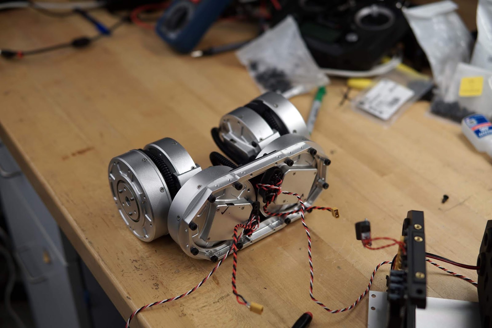
Actuator with stator and gearbox installed:

I made several minor design mistakes I had to fix. Some holes in the sheet metal were 1mm off, so I made this fixture for re-machining the holes. Small mistakes like this sunk a huge amount of time, because each on has to be fixed between 50 and 150 times. Fortunately everything was salvageable.

Most of the actuators with stators and planetary gearboxes installed:

Part of one robot body with computer, CAN interface, IMU, RC receiver, and power supply:

The glorious actuator cabinet:

Computers and CAN breakouts:

Power supplies, body center-plates:

Belts installed, ready for tensioners and outer half of the leg clamshell.

A mostly assembled leg:

A nearly complete robot, waiting for the last few wire-management steps and final body assembly:

One robot during electrical and software testing, before final assembly:

Half a robot's worth of actuators:
Final assembly step of attaching the legs to the body:

Robot with top panel removed:

A pair of robots ready for final testing:

Most of the new robots lined up on the lab treadmill:

I just love these detailed pics!
ReplyDeleteCould you share how you decide on belt tension and how do you properly measure it? What's the center distance between the pulleys compared to belt length - how much slack do you introduce? During any of the stressing motions (e.g. backflips) did you experience the belts jumping teeth?
There have been no belt-skipping or breaking problems. The robot has tensioners, so I left just a little bit of slack and adjusted the tensioners by ear. The Gates Poly Chain Design Guide has tension information for 8 and 14mm pitch belts, but not 5, but you could probably scale their data appropriately. The gates guide also shows several techniques for measuring tension.
DeleteFor this application it's important to use the belts with kevlar tensile members, not fiberglass, as they're stiffer, stronger, and handle shock loading better.
This comment has been removed by the author.
ReplyDelete"Small mistakes like this sunk a huge amount of time" I really agree with that.
ReplyDeleteNow I'm following your path to build a such an masterpiece.
I will share you after I finish this job ^ ^.
Hello Ben,
ReplyDeletevery impresionant, was a big editing job that took you several weeks, an accelerated video editing will have been interesting, I noticed you change the design for the actuator, now you add a new big ball bearing and close the planet gears (grease), but I was wondering if you removed 6702 that was inside the rotor,
one last question the PSU is still for a Kobalt 24V batterry only and if we can find PSU's eagle PCB design
If not good luck in your projects, and thank you for your blog
Yes, I removed the 6702 bearing now that there are two bearings directly supporting the planet carrier.
DeleteSorry, I don't have the PSU design posted anywhere right now.
Any chance of doing a YouTube video with parts list for the legs?
ReplyDeleteI didn't film much of the assembly process. Plus I don't really like youtube as a documentation medium - it's just free video hosting to me.
DeleteHi Ben,
ReplyDeletehow are you doing?
I was just wondering, could you by any change share with us, what kind of motors did you use for the Mini Cheetah robot? That would be awesome, since I want to do some experiments with them and build some kind of robot eventually.
One more question, did you buy all of the planetary gears on the internet or are they custom made?
Thank you so much what you're doing and keep up the good work.
Jakub
Hi, Great jobs.
ReplyDeleteWhere did you buy the gear sets? Misumi gears are two expensive. If you know any cheaper vendor please let us know.
What kind of IMU are you using?
ReplyDeleteHi Ben, amazing and inspiring work. Curious, what mechanism(s) is the belt tension actually applied with? Reason for asking is I've been working on a legged project myself and the knee actuators work on a belt drive as well, but getting adjustable tension adjusters involved have created more bulk than I'd like. Is it safe to assume you're using a spring loaded idler pulley of some kind? Keep up the fantastic work.
ReplyDeleteThere's a pair or rollers inside the leg that get adjusted inwards with a set screw. Spring loaded tensioner won't work well, as there is reversing tension on the belt.
DeleteThat is super coincidental because I failed to notice you had responded until today, and that same solution is what I chose to use in a recent iteration. I came to it originally from a belt tensioner in a Cadillac that my father in law needed help with recently. Too funny. Sounds like I am on the right track to getting similar results! In my current prototype I’m actually using those dirt cheap “flycat” bldc motors you wrote about in your past blog (because, I enjoy a good challenge in quarantine why else?), however I needed to increase the gear ratio to get a jumping effect similar to your robot. Of course, this quadruped is scaled down vastly.
DeleteI failed to notice the entire thesis was available for viewing via MIT's website where this was mentioned until after your reply. Lol. Appreciate it nonetheless. It's strange to me that I came to a similar conclusion, but perhaps not as elegant because I cannot figure out where they are happening in the photos I'm looking at, if this is a secret sauce no worries if you don't want to reveal in full detail haha. I saw something resembling a filament 3d printer extruder spring arm on one of your photos (on the thesis paper).. and couldn't help but wonder what was going on there. I came to a similar conclusion myself which kind of freaked me out because I didn't even see this comment reply till about a month later. Ahem. Ben, are you placing subliminal messages into your CAM/CAD work? (thanks for your inspiration however it shows itself lol :))
DeleteHa, nice! Funny how that happens.
DeleteThere actually aren't any pictures of the belt tensioners in this post. In the photo where the two legs with belts exposed are visible, the tensioners are not yet installed. I didn't change anything from how they were shown in my thesis, other than putting a sleeve around the tensioner bearings to prevent gaps where the bearing chamfers meet.
Okay. In my most recent build I ended up keeping pulley ratio the same from actuator you knee joint, mainly because I geared down to a 12:1 ratio but somehow achieved very quick action on the leg joint. Was there a reason besides backlash that lead you to add that extra bit of gear down on the belt drive ratios? I’m using closed loop belts and the upper member length just looked too funny given the constraints I set by buying probably the wrong length belts before I tested more, lol (they were a good deal on eBay what can I say).. I can always go back later and change this out but I was curious why this slight reduction was chosen on your belt drive, because I didn’t notice any noticeable backlash pitfalls in my case.. I’ll send you a link to my build once I’m done with assembling all 12 actuators and collect all my photos into one spot, would love to hear any feedback if you have a chance. Thanks again for being so transparent man. There are a lot of parallels the more I read into the Mini Cheetah that I Wish I would have came across your blog 3 years ago when I started this project as ultimately a one man band! Massive respect.
DeleteNothing to do with backlash. The knee joints end up taking most of the weight of the robot, so it's helpful to have a bit more torque there than at the other joints. Just standing with the feet directly under the hips for example, no hip or abd/adduction torque is required, only knee torque.
DeleteMakes sense. I’ll probably have to try that route if this doesn’t work to my liking. I’m borrowing your idea to use squash balls as a foot pad, I took a wild guess based on your measurements of 40mm that they ought to be the “two yellow dot” type, was I correct? I found them on Amazon for pretty cheap, but I noticed they only had marginal bounciness (using the same brand you guys used). Were there any tests using them without any expandable foam filling? Curious.
DeleteYep, two yellow dots. The lack of bounciness is actually why I chose them. No tests without the foam filling, but in retrospect I think it would work fine. I'd still cut it open and stuff a hard insert in the middle though - I think it would be too soft if you tried to just glue a "cup"-shaped thing to the outside of the ball. TBH, very little design work went into the feet, and I'm sure there's better ways of doing it, but the squash balls are convenient.
DeleteSweet! Since I’m still milking out the pcbs for each actuator I have only made one experiment with these things but I attempted using loctite brand expanding foam (because it was there) and a sorta similar 3d printed insert and it was disastrously ugly. On the positive side, the acetone I used to remove the excess foam, also removed the branding logo off of the ball, so there’s what I learned. Lol. With that said, I’ll likely just try something along the lines of what you just said. I was contemplating how the balls of our feet are basically “unpadded” and they tend to hold up to a lot of abuse so maybe there is some sort of stability advantage we gained by growing this way evolutionarily. Thanks for confirming, it gave me a sense of a “win” with the two yellow dots guess. Hah!
DeleteHi Ben, really an excellent job. Please let me know who are the groups working on the 50 mini cheetah prototypes you built, so that to change opinions/ comments, suggestions on the robot improvements for research purposes. Thanks a lot Paolo
ReplyDeleteHi Ben, In browsing around I came across your MIT Cheetah project and think that it is very exciting work so I decided to read over your Thesis which is a really nice piece of engineering work. On question that I had was in that you mentioned using another motor that had similar spec to the "T-Motor U8" but which cost 1/3 the price. Maybe I missed it, but I did not see the name of that motor or the manufacturer. Could you please tell me what it was? Thanks
ReplyDeleteI bought them from iFlight, but several other vendors make 8108 size motors as well, DYS, Sunnysky for example.
DeleteHi Ben! I have a couple of questions:
ReplyDeleteFirst, how did you decide on the 1.55:1 speed-reducer ratio?
Second, as you previously mentioned and as I found while looking through the Gates Poly Chain Belt Drive Manual, Gates does not providing sizing information for their 5 mm pitch belts. How/where did you source the 5mm pitch belts? In addition, where did you source the subsequent sprockets?
The 5mm pitch allows for the same speed ratio with smaller diameter sprockets, which is ideal for my application. Is that also why you selected the 5mm pitch synchronous belt and sprockets, rather than the 8mm pitch synchronous belt?
Yeah, 5mm polychain isn't really documented for some reason. The ratio was chosen based on a combination of scaling data from Cheetah 3, and packaging. I originally tried 12:18 rather than 18:28 pulley ratios but it wasn't stiff/strong enough with the smaller pulleys.
DeleteI got the belts from Royal Supply
https://www.royalsupply.com/store/pc/Gates-5MGT-535-09-Poly-Chain-GT-Carbon-Synchronous-Belt-9270-5720-p16813.htm
And pulleys from Misumi
https://us.misumi-ec.com/vona2/detail/110303274110/
I did aa bunch of post-machining to the pulleys though
The minimum pullet diameter for 8mm pitch belts was too large for this robot.
Thank you so much for the feedback! I was looking at Royal Supply, so I'm excited to hear that you sourced your belts from them.
DeleteDo you have any professional social media platform such as LinkedIn? I would love to ask you a few more questions about your knee design, and possibly any post-machining you did to the pulleys.
My personal email is celwell20@gmail.com, but feel free to look me up on LinkedIn as well. My name is Clayton Elwell, and I am a undergraduate mechanical engineering student at California Polytechnic State University, SLO.
Nope, no social media.
DeleteYou can fill out the contact form:
https://build-its-inprogress.blogspot.com/p/about.html
Hey Ben amazing work. I had a quick question about the stator. Could you tell us how you managed to remove the of the shelf stator casing from motor before press fitting the front housing?
ReplyDeleteFor building 10 robots I ordered the stators without housings.
DeleteFor the first robot, I remove the stators by using a hacksaw to cut 4 grooves through the aluminum housing the stator is pressed onto. Then I used a hammer and flat driver to bend the 4 tabs left from sawing inwards, away from the stator. Only took a few minutes per motor.
awesome thank you so much. This really help
DeleteHey Ben, could you share what you used for the belt tensioners? I know that a belt tensioner is just a roller bearing on an adjustable arm and I was wondering if you found a place online that you ordered the belt tensioner from? Seems like most belt tensioners are a little big and not easily adjustable. Any tips would be helpful. Thanks!
ReplyDeleteThey were custom - just a thin-walled with a small metric bearing pressed in each end for the roller. The rollers were mounted on small custom-machined "swingarms" that could be pivoted with a set-screw for adjustment. There are some pictures of the inside of the leg with tensioners installed in my thesis.
DeleteDear Ben, can I please ask which belt width did you use? Thank you so much! David.
ReplyDelete9mm
DeleteThank you Ben. Your work is marvelous and inspiring. David.
DeleteDear Ben, do you think the sleeve, covering the tensioner bearings, should also have an aligning flanges, to keep the belt in place (so the sleeve forms the shape of a wide U in which the belt is both supported and aligned)? Thank you, David.
ReplyDeleteI don't think it would hurt, but I didn't find it necessary.
Delete