In the picture below, the heatspreader is on the left, and cover on the right: The bar across the bottom sits on top of the FETS, the square in the middle sits above the DRV chip. I left a 0.1mm gap between the FET-bar and the top of the FET package, which gets filled by some .5mm thermal pad. This allows for some variation in the height of the transistors once they're soldered down, and the compression of the thermal pad means there's a fair amount of pressure pushing down on the top of each transistor.
Motor Controller Sandwich:
The two little holes let through light from the two indicator LEDs on the board.
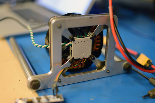
I made a Special Motor Controller Cover of Science to help out with thermal camera-ing. It has a 1.5mm hole drilled above the center of each transistor, so that I can see through the cover with the camera. I stuck it on the same controller and motor I used for the last round of testing. I was able to use a needle to cut away the circle of thermal pad at the bottom of each hole, so you can see straight through to the tops of the FET packages.
Here's an example image You can see the transistors clearly through the holes. The bright spot on the cover where point Sp2 is is where I applied some matte black paint to get the emissivity of the aluminum cover closer to 1.
The cover was extremely effective. Here's a 30A test. By the time the motor windings reached 70 C, the FETs were all under 48 C, and there was only a 1.6 C difference between the hottest and coldest transistors. For reference, in my last tests without the cover, by the time the motor reached 70 C at 30 amps, the FETs were between 67 and 72 C.
Going a little harder, here's after running 33 A until the motor windings reached a rather uncomfortable 80 C. There's a 5 degree drop between the top of the transistor and the surface of the cover.
That's all for now.


Hi Ben,
ReplyDeleteWhat's the model of the FLIR thermal camera you're using?
How can you set accurately the location of your points Sp1, Sp2,etc?
Any advice on the camera mounting support?
Thanks,
Hello Ben. Huge fan of your work! Any updates on the driver? I would like to try building the inverted pendulum like you did mainly as an exercise to educate myself in BLDC motor control. I know you published the files for the previous type of controller. Would your recommend me using that or to wait for this newer one?
ReplyDelete