Whereas the small dyno is good for 10 N-m of torque and 6000 RPM, this one will be good for 60 N-m and 15,000 RPM (although not simultaneously), and somewhere around 30 kW power.
First step was acquiring the appropriate torque sensor. The DC-output one I have on the small dyno is extremely convenient, because you can just measure the output with a DAQ or A/D, but the AC coupled ones are much more common on Ebay. Unfortunately, the readouts for the AC torque sensors are very expensive and hard to come by. A pile of really big, really cheap DC-operated torque sensors showed up on ebay for $28 apiece, so we got one and the MIT FSAE team collected the rest of the lot.
10,000 inch-pounds! (~1100 N-m) and 8500 RPM. With ~2" shafts on either end. Not actually very useful.
We gutted the readout electronics from it:
And shoved them into this AC-operated 500 in-lbs, 15k RPM torque sensor. This thing is pretty much perfectly matched to the Sonata HSGs.
Several months ago I went on a shaft-coupling machining spree, making the two lovejoy couplings for the torque sensor, and two more for a pair of the HSGs:
The shaft couplings all have internal keyways, which I manually shaped on the lathe. I ground HSS inserts for a boring bar, locked the lathe spindle, and shaped the keyways with the carriage feed, retracting the cross slide ~.005" per stroke, with occasional spring passes. The keyways can be easily widened by shifting the tool up a little on the toolpost.
I've been pleasantly surprised by how nicely the keyways turn out with this process. Even for some big 6mm keyways for pulley hubs for the Big Kart, the results were very clean.
The shape of the Sonata HSGs leaves much do be desired. While at least they are completely sealed and have real shafts, unlike the motors in most hybrid transmissions (i.e. the Prius or Fusion motors, which are tightly integrated into the powertrain, and have to be freshly rehoused to be used at all), they are very strangely shaped. Their cast aluminum housings have almost no flat or square surfaces, making them very challenging to measure. I was able to eventually find the positions of all three mounting feet and the shaft by using a surface plate, a height gauge, a set of adjustable parallels, some custom-turned shafts which press-fit into the bolt holes, and one sacrificial motor housing which was bandsawed in half. The last measurements, which located the motor shaft with respect to the feet, could not be reasonably made without referencing some of the machined bores on the inside of the housing.
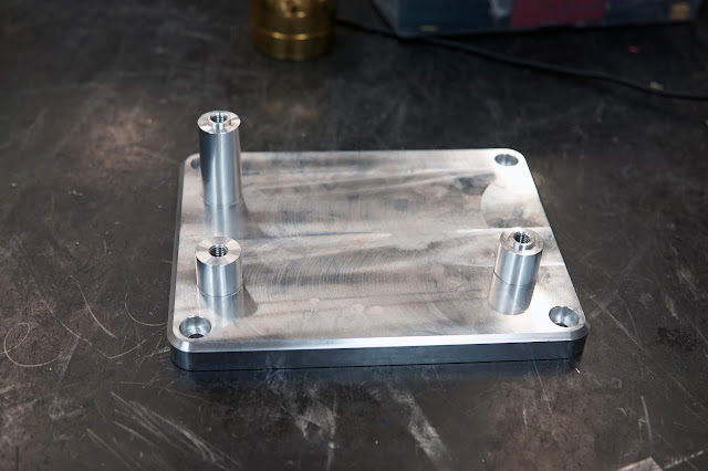
I machined a pair of HSG mounts. The feet were turned on MITERS's newly acquired Hardinge HLV lathe, and the base was CNC milled on the Super Mini Mill. The turned feet press-fit into locating pockets on the base, and are fastened from underneath. The two diagonal feet have 14mm bosses on top, which mate with corresponding 14mm locating bores in the bottom HSG casting.
The underside: Since the parts needed to get flipped over anyways, I did some gratuitous pocketing on the bottom:
The painful measurement process paid off. The motors dropped into place perfectly:
Like the small dyno, the base of the big dyno is a huge slab of aluminum. I started out with a big optical breadboard I got for free last fall. It's a roughly 1'x3'x1" cast aluminum sheet, with a 2" grid of 1/4-20 holes in it. Somehow this plate was extremely warped, with roughly a 1.5mm height difference between the center and the edges, in the long direction. I set up the plate on the bridgeport, and faced the hole thing:
The plate was substantially longer than the x-axis travel of the mill, so I had to swivel the column around half way through to face the whole thing.
To fixture it, I machined a little step into each end. This way the step clamps hold it down hold right at the edges, and don't put any bending stress into the plate:
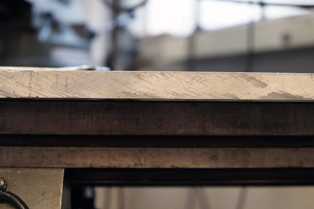
Here you can see the huge gap between the center of the plate and the table of the mill:
I was expecting the plate to continue warping as I machined it from residual stress in the material, but by some miracle it didn't. Once I faced the first side, it just stayed perfectly flat. I didn't even bother facing the underside, because nothing will be mounted to it.
Pile of chips post-facing:
I squared up all the edges as well, and gave the corners a healthy chamfer.
Here's the absorber mounted:
And a preview of the whole assembly. I still need to make the foot to space the torque sensor up appropriately. The first motor we plan on dyno-ing on this thing is the HSG, so we can squeeze every last drop of performance out of the Big Kart, but after that , the motor on the right will be swappable for any other motor which fits. The plate is mounted to the top of a cart by some rubber shock mounts to vibration isolate it.
In related news, the Big Kart is frighteningly fast now, thanks to the double-motors, Polychain-based drivetrain, and new lookup tables based on the stall data and better inductance measurements. Hopefully we'll get some decent videos of it, now that the weather's shaping up. Here it is after some thrashing by Michael


