

I'll jump straight into the design, and then go back and justify it.
Here's a motor:

Here's what the stator looks like. This winding pattern is fairly incomprehensible from this picture, so I'll explain it more clearly later:

The stator consists of two thin fiberglass disks wound with litz wire, sandwiched on either side of another fiberglass disk, which is bolted to an aluminum hub.
Here's half of the rotor. The magnet arrangement is a 12 pole-pair, 90 degree halbach array arrangement assembled out of identical .25"x.25"x1" N50 magnets.
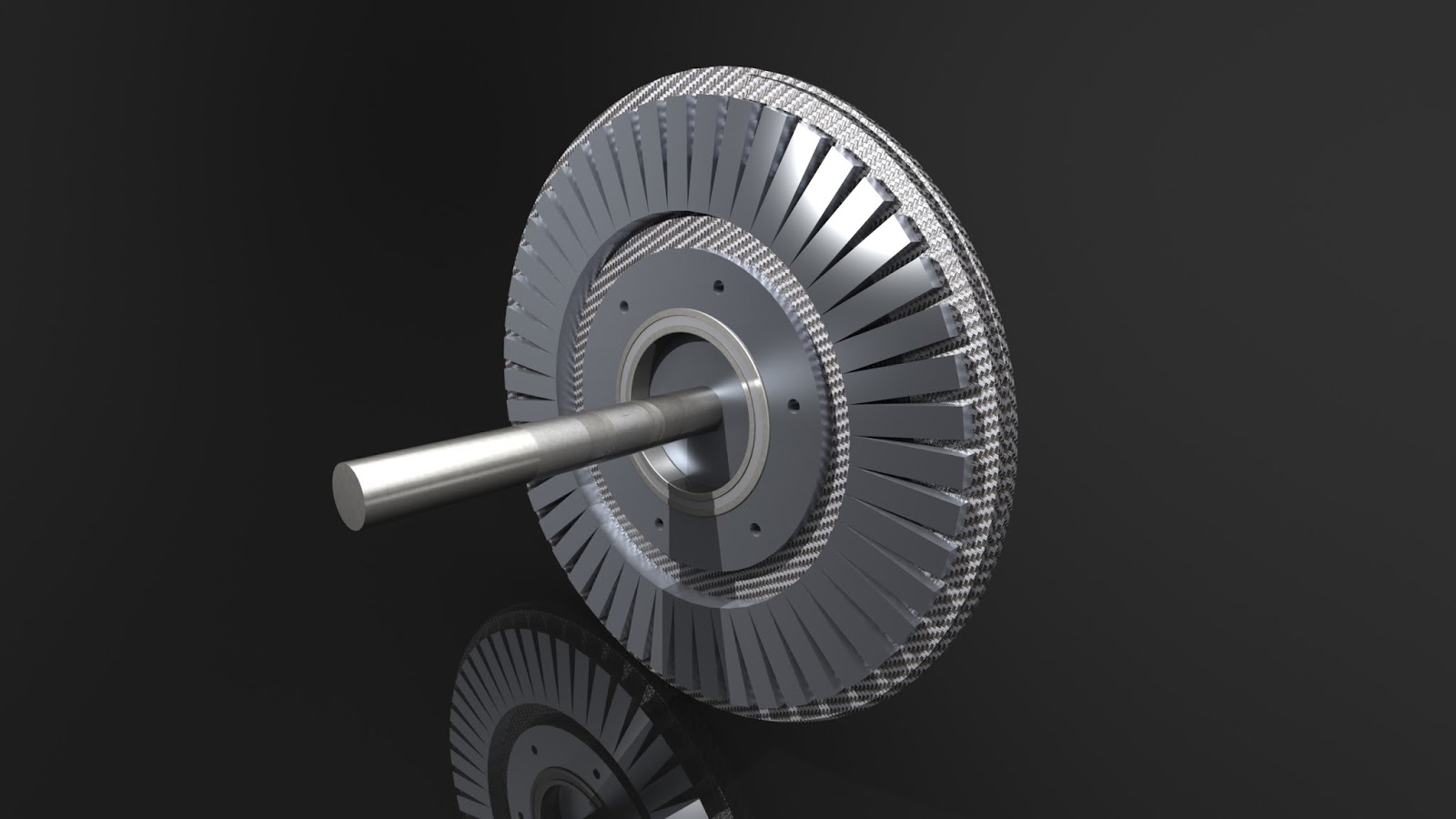
And the whole rotor (minus the cylindrical shell between the halves). Because of halbach array magic, the rotor can be made out of something awesome like carbon fiber, instead of steel. Honestly, there's little to no weight savings here using carbon fiber over aluminum, but A) carbon fiber is awesome, and B) techx funding is a great excuse to buy fancy materials.

To explain how this thing actually motors, I'll start out by explaining the windings. I spent a lot of time thinking about how to wind such a motor. Not being constrained to wind around a laminated steel stator means there are lots of options.
My first thought was to waterjet three identical winding out of sheets of copper, and epoxy them together 120 electrical degrees out of phase. Copper sheet windings would allow for variable wire width, so the conductors could get wider as the radius increased. Also, the end turns would not be constrained to the width of the rest of the winding, so they could be made much fatter. I knew eddy current loss in the windings would probably be a problem with this design, so I spent lots of time running through different winding geometries in MATLAB to figure out just how bad the losses would be. Then I gave up with that idea.
Turns out there's a really cool masters thesis on basically this exact thing. It's great at very low speed, since the copper fill factor is extremely high, but at any reasonable speed it gets destroyed by eddy current loss in the solid copper conductors. Also, it's probably the most beautiful set of windings I've ever seen.
Next option is to go the to the other end of the spectrum, and use litz wire to wind the stator. Extremely fine insulated strands should nearly entirely eliminate eddy current loss in the conductors. There are a bunch of possible strategies for winding the stator. Concentrated windings, like Shane's LEAF motor makes winding much easier, but there's a lot of unused space in the stator where copper could go. To think about winding configurations, I mentally stretched the motor out into a line. My first thought for a distributed winding pattern looked something like this:
With one phase, it's really easy to see how how the lorentz-force action works:

To make it three phase, just copy and paste that same winding pattern twice, shifting by 120 electrical degrees each time:

Wrapped around into axial-flux, a phase looks like this:

Unsurprisingly, this has been done. Here's a great example of a stator which appears to be made this way. There are a few things I don't like about his winding pattern though. First, there is quite a bit of copper in the end turns (although the end turn to active copper ratio goes down as you add more poles). Also, the end turns have to overlap each other with three phases, meaning the inner and outer rings of the stator need to be thicker than the active region.
Here's another idea. Turns go diagonally across each pole, instead of up and over:

That's interesting. It's pretty intuitive that this winding pattern will have a lower torque constant than the rectangular winding, since each turn overlaps the whole sinusoidal field. To the first order, I'd expect the peak torque produced by a phase to be lower by a factor of roughly 2/π ((integral from 0 to pi of sin(x)) / (integral from 0 to pi of 1)) However, it also clearly will have lower resistance than the rectangular winding. Also, there's no end-turn overlap, so stator can be made a constant thickness throughout.
Just by looking at it, it's not exactly clear whether the lost resistance makes up for the lower torque constant, but it does seem easier to build, so I designed a motor around it and then figured out how it should perform. Fun fact, it turns out this is pretty much how Faulhaber motors are wound, but those are radial, not axial. I haven't seen any axial flux motors wound this way.
On to actually analyzing this thing. First I took a look at the magnet array in FEMM. I unrolled the motor to a line at its average radius, since FEMM is 2D. I didn't bother with looking at the entire magnet array, and just simulated a few pole pairs:

The normal flux density around the middle of the airgap looks like this. Peak normal flux density of around .75 T. Not too bad for a 10mm gap between magnet surfaces. Looks pretty sinusoidal, too (ignore the edges).

Now I know what the field looks like. Rather than doing the rest of the simulation in FEMM, which is certainly possible, I did it in MATLAB because I have little interest in learning how to do FEMM Lua scripting.
My stator is wound for 12 pole pairs, and 5 turns per phase. However, the turns are evenly distributed about the circumference of the stator, not concentrated on top of one another. Stretched out into a line (again), the winding pattern looks like this:

All the turns in a phase are in series with one another.
To figure out things like back EMF and torque constant I took another LEAF (ha!) out of Shane's book.
Method 1: Lorentz Force
The most intuitive way to look at the torque constant is probably doing ILxB on all the wires to find the force on them for a given current, and adding up the wires that correspond to each phase. This method resulted in a torque constant of .0752 N-m/A for one phase.
Method 2: Looking at Flux Linkage
This was was definitely less intuitive, but produces some more information. Here's how it works:
- Define the shape of one turn of one phase, and define a sinusoidal flux density for a couple pole pairs.
- Integrate the flux density over the area of the turn, for flux linked by one turn of one coil.
- Virtually shift the coil a little bit along the magnets, and repeat the above calculations. Repeat until the coil has shifted by 2π.
- Repeat for each of the 15 coils (5 turns per phase, 3 phases), which are all offset from one another. This gives the linked flux vs electrical angle of each coil, which looks like this:

- Take the derivative and multiply by an arbitrary electrical frequency. I used 1256 rad/s, which corresponds to 1000 mechanical rpm with a 12 pole pair motor. This produces the voltage induced on each winding vs electrical angle.
- Add up the voltages of the coils which are part of the same phase:

- Back EMF constant (Ke) and torque constant (Kt) are equivalent, for a phase Kt of .077 N-m/A. Hey look, that's basically the same as before!
To see what would happen when wye-terminating the motor, you can subtract two phases from each other, since they are connected in series but joined at the ends:

Wye terminated, I should expect something like .13 N-m/A, or 72.5 RPM/volt. Seems pretty reasonable.
It's easy to compare skewed vs straight windings this way, also. For my particular motor geometry, using straight windings gives a 30% boost in torque constant, and a corresponding 30% increase in phase resistance. So overall, it actually produces a slightly higher performance motor, since motor constant (here defined as Kt/√resistance) is higher.
Actually building this thing:
Most of the motor parts were made on the MITERS CNC mill. Here's the fancy-looking end cap that joins the rotor to the shaft:

Plates that connect the thin section can bearing to the rotor:

The stator parts were routed out of 1/32" Garolite using a 1/16" carbide endmill borrowed from Nick. I messed up these parts a few time (trying to fit too many turns on the stator, messing up winding, etc) so I've gotten really fast at making these. I experimented with a couple methods for fastening the fiberglass to the mill. I bolted a sheet of masonite to my milling fixture, and adhered the fiberglass using spray adhesive, hot glue, and double sided tape. In the end, I like the double sided tape the best.


Two phases:

And all three:

I squished the windings in the mill vice to get them nice and flat:

The two stator windings were epoxied together with high temperature epoxy, clamped between two aluminum forms, and baked to cure:

Rotor parts were routed out of .1" carbon fiber sheet using the same 1/8" endmill. The sheet I used was laminated from unidirectional layers, and the top and bottom edges came out a bit fuzzy:

Filing with a diamond abrasive file cleaned up the edges:


Beginning the magnet array:


All the north-south pairs glued down:

Magnets really don't appreciate being forced into a halbach array, so I stuck a big steel plate on top of the array (with a thin plastic buffer between), and slid the sideways-pointing magnets in from the side, positioning them with a 3d-printed jig:

Everything was then slathered with epoxy and cured:

The steel disk was sheared off by tapping it with a hammer.

The aluminum hub holding the stator was the only component that was manual machining-intensive:

I paralleled the two halves of the stator, wye terminated them, and attached one of the two rotor disks for testing:


It's easy to compare skewed vs straight windings this way, also. For my particular motor geometry, using straight windings gives a 30% boost in torque constant, and a corresponding 30% increase in phase resistance. So overall, it actually produces a slightly higher performance motor, since motor constant (here defined as Kt/√resistance) is higher.
Actually building this thing:
Most of the motor parts were made on the MITERS CNC mill. Here's the fancy-looking end cap that joins the rotor to the shaft:
Plates that connect the thin section can bearing to the rotor:
The stator parts were routed out of 1/32" Garolite using a 1/16" carbide endmill borrowed from Nick. I messed up these parts a few time (trying to fit too many turns on the stator, messing up winding, etc) so I've gotten really fast at making these. I experimented with a couple methods for fastening the fiberglass to the mill. I bolted a sheet of masonite to my milling fixture, and adhered the fiberglass using spray adhesive, hot glue, and double sided tape. In the end, I like the double sided tape the best.
Getting the winding down took a few tries. The motor was wound with 20x5x38AWG litz wire. Since litz wire is twisted, when folding the wire around the opposite side of the fiberglass winding form, the wire behaves strangely. Winding one direction, it bends parallel to the sheet, and the other direction it bends perpendicular to the sheet. I chose the wrong direction to wind my first one, and it turned out terribly messy as a result. Next time around I realized winding the other direction would be much easier, and switched.
Here's one phase:
Two phases:
And all three:
I squished the windings in the mill vice to get them nice and flat:
The two stator windings were epoxied together with high temperature epoxy, clamped between two aluminum forms, and baked to cure:
Rotor parts were routed out of .1" carbon fiber sheet using the same 1/8" endmill. The sheet I used was laminated from unidirectional layers, and the top and bottom edges came out a bit fuzzy:
Filing with a diamond abrasive file cleaned up the edges:
Beginning the magnet array:
All the north-south pairs glued down:
Everything was then slathered with epoxy and cured:
The steel disk was sheared off by tapping it with a hammer.
The aluminum hub holding the stator was the only component that was manual machining-intensive:
I paralleled the two halves of the stator, wye terminated them, and attached one of the two rotor disks for testing:
A couple things are apparent. First, it definitely wants sinusoidal commutation. Nice and noisy with the hobbyking controller.
Also, the motor displayed astoundingly high loss at high speed. Just spinning the rotor by hand, it was easy to see how quickly the rotation was damped. Sounds like eddy current loss. By chucking the rotor in a drill and spinning it, I could even feel the windings warming. But wasn't the point of using fancy litz wire to eliminate that? At first I thought the process of oven-curing the epoxy had destroyed the litz part of the litz wire. I had set the oven to 120 C, so maybe there was a chance the temperature control loop overshot to 150 C, which would be dangerously hot for the insulation.
I made another stator. Before epoxying everything, I quickly tested it. And it displayed the exact same drag as the epoxied-and-baked stator. So something else was up. On a hunch, I unparalleled the two halves of the stator from each other. And the issue disappeared. Scoping corresponding phases on the two stator windings confirmed my suspicion. With only one half of the rotor in place, the two halves of the stator experience very different fields from the magnets on the rotor. Since they were wired in parallel, this caused massive circulating currents between the two halves of the stator, causing the drag that felt like eddy current drag.
Looking at the two curves on the scope screen, the yellow trace is the phase close to the rotor, while the blue one is the phase farther away. The farther away phase has less than half the voltage induced across it.

I un-terminated the first stator, and confirmed that it was also fine. Since the problem is due to the asymmetry of the rotor with only half of it installed, the obvious solution is just finishing the motor by adding the other half of the rotor. The two sets of windings should then be happy and symmetric. If the loss is still a problem, the solution is to series the two windings instead of paralleling them. This will make the motor even slower, but should completely fix that loss.
Now I just need to make a ring to separate the two halves of the rotor, so the thin-section bearings don't explode due to the magnetic attraction between the two plates. And find something silly to stick the motor on. And build another one, since I've already gone to the trouble of building a second stator.
Great work, love the stator design!
ReplyDeleteI am building an AFPM and looking at what design to use. My plan is to water cool the stator to be able to run more power, do you know how much this motor can produce continuously?
Why do you have two discs with Litz and a center carrier, is it for structural reasons only or is there another reason? My thought is that the airgap could be decreased a little with a single garolite disc with litz threaded through holes. //Cheers
I'm not sure how much continuous power it can produce, because I haven't done thermal testing. Also, I don't have a motor controller that can efficiently drive the motor (super low inductance means higher RMS current and higher loss for a given torque). Basically you need either a controller that switches really fast, or to add some series inductance to the phases to make the controller happy.
DeleteI used two discs plus carrier for structure and mostly ease of assembly. The airgap and/or copper fill ratio could certainly be improved by removing some of the g10 from the stator, but it would make winding and assembly more challenging.
OK, i see.
ReplyDeleteI've seen some posts regarding issues with low inductance but don't know the reasons behind. It's a shame if you put all that work into a motor and cannot drive it efficiently. Must be some controller options out there? Otherwise i'd have to build a more classic stator if controllers are an issue.
The standard way to drive such a motor is to add series inductance. This is what servo drive companies do (Advanced motion controls, maxon, etc) for driving coreless motors. If you don't care too much about weight, this is a perfectly good solution. Otherwise, I might eventually get around to building a high switching frequency controller.
DeleteHi, you did great work and there's a lot of nice pics. It would be nice that you analyse with FEMM the results when you displacd the upper stator to the next PM? Lets say you have winding A of the upper stator align to the N pole of the PM and the lower winding A of the stator is align with S pole of the PM. This is the normal way of doing it. What I'm suggesting it's to align the upper winding A to the S pole of the next magnet right beside (this will implicitly realigned windings B and C). Note that you must change the + and - of the upper windings to work. For sure you will gain a lot in flux density because 2 PMs are used instead of 1. By the way, you design is great! Thanks for sharing.
ReplyDeleteHi,
ReplyDeleteHow do we calculate the stator vs poles for such design? I once made a motor with 87 stator slots and 8 poles, tried it up with a sensorless RC controller, it just kept making noise and didnt turn, tried turning with hand wen stopped it started moving in other direction for few degrees and stopped, few minutes later the Capacitor on the controller popped out :P CAn you help me on this?
How to calculate what series inductance should be added on to this to use with a high frequency controller?
Thanks :)
Nish.
Hi Ben,
ReplyDeleteI am a Mechanical Engineering student and really liked your design. I am thinking to build a Axial flux motor for my final year project. Can you please send me the CAD drawings of this motor with assemblies??
Thanks you
Rahul
If it's can help...
ReplyDeletehttp://www.ata.org.au/wp-content/uploads/marand_high_efficiency_motor.pdf
...the width of 3 phases is higher than the width of one magnet...by Csiro"There a 3 phases in the width or(of) a single magnet."...
ReplyDeleteThis comment has been removed by the author.
Deleteis it mandatory to use litz wire alone? or can i use enamelled wire?
ReplyDeleteBtw, awesome work, thanks for sharing the info.
Using solid-stranded wire of equivalent gauge will result in massive eddy-current losses at speed.
DeleteThanks for the quick response Dear Ben Katz. Unfortunately litz wire is not available in a part where i live. Still let me try , meantime, if you have any other clues , please do let me know
DeleteThanks
One can create your own litz wire from multiple strands of enameled wire. Google how to make litz wire.
DeleteHi, I'm trying to experiment with making a halbach array alternator. This came up in the Google results. If I may ask, how well does such an arrangement hold up if being used as a generator?
ReplyDeleteIts great for projecting magnetic field lines further out to reduce stray flux causing more magnetic lines of force to cut through your coils. But the additional magnets conduct magnetic field lines through the additional magnet. One can yoke the magnetic field lines through a steel plate backing more cheaply.
DeleteHey man I know this is very old, but could you explain why litz wire is so necessary in this type of motor? I am having a he's time understanding why the lack of an iron stator males the copper so much more susceptible to eddy currents as compared to a iron core axial motor. Thanks a ton in advance.
ReplyDeletehow did you polarise the magnets so they would be suitable for the Halbach array?
ReplyDeleteHi. I know you did this a while ago. What are your thoughts on effect of straight rectangular magnets vs wedge shaped magnets on Halbach effect? Do you think using wedge shaped magnets would increase performance? Thanks.
ReplyDeleteYour stator has a fatal flaw. Your first phase has 5 turns wrapped in such a way that it creates 24 coil poles not 12. Look back at your picture of your 1st 5 turn coil winding and see through the plastic and you will count 24 coil poles.
ReplyDeleteYou can use that stator with 24 pole rotor though. Instead of a 12 pole hallbach array, you could just rearange your 24 magnets as 12 n and 12 s poles, or you may go with a hallbach array with 48 magnets forming 24 poles.
Read more carefully.... Everywhere I say pole pairs, not poles. 12 pole pairs = 24 poles. The stator and rotor are both correct and work as expected.
DeleteI see where i made my mistake. The issue was i didn't see this picture.
Deletehttps://3.bp.blogspot.com/-rLR4La2bfLI/VNZ8chzrmLI/AAAAAAAAJvA/Ux2Gqi5V8pU/s1600/20150201_203958.jpg.
That lead me to think you had a 12 pole halbach array. Vs 24 pole halbach array.
Also, despite what people say, i like to see what they did. Sometimes, the two are not the same. My mistake was that i overlooked one photo, and came up with a wrong conclusion of a 24 magnets halbach array having only 12 poles. When in fact the picture i missed was 48 magnets halbach array with 24 poles.
DeleteThis comment has been removed by the author.
ReplyDeleteHi so just by using thicker magnet, will it give you directly an higher torque value ? Very great projet.. don't know if you had done more experiment too.. Thanks in advance
ReplyDeleteI love the design. I am in the middle of building a motor similar to his.
ReplyDeleteWhile mine also uses a faulhaber winding on an axial flux stator plate, my motor has only 1 rotor plate with 12 poles, and my one three coil stator plate lays ontop of a steel banding wound into a coil to increase the inductance of the coil for operating low speed. The steel banding is painted on both sides so that it does not complete a circuit, thus limits eddy currents.
I have to say, using 16 gauge non-litz wire is difficult to wrap nice and neat. Furthermore, it would have been better for me to go with more than 12 poles. 24 poles would have had 1/2 as many turns per winding around the flattened toroid's diameter, but the angles would have been easier to wind. Also, absolutely use Litz wire.
Actually, is the faulhaber by being more widespread... do better than having coil done in teardrop shaped ?
DeleteOn the Litz, was is the same eddy rejection if using a litz wire or 1 single thiny wire (like the one litz wire is build with) ? Like it's 1 large winding a 1 continuous wire vs a bundle of small wire wrap around... Thanks.
"is the faulhabor better than a tear drop?" I do not know what a tear drop coil is to comment. On using litz, in theory and when used appropriately, it would do a better job of reducing skin effect at high frequency. The downside is it has a lower copper fill rate. I am not as certain that reduced skin effect would benefit my low speed motor much, but maybe it would considering the BLDC controller's uses pulse width modulation switching at on and off at a fast rate. Considering the difficulty in wrapping 16 gauge wire on a flat torus and no CNC to cut grooves on the inside and outside, I decided to use nails on a flat board and wrap the wire on the nails. Doing it this way causes the wires to takes up more space on the inside diameter of the torus. thus there was just enough room on mine for three coils with 12 poles and 4 turns around the torus's major diameter. The motor works well, it runs smooth, self starts, and has good torque considering the build. I will be doing test on it later.
DeleteKeith- JFPlanes probably meant the classical coil shaped like spool, in case of axial flux generator it is wedge or tear shaped.
DeleteI think radial wires in active area(where magnets are moving) is essential for high efficiency. The waveform coil should be thin too... Maybe more than 3 phases would be beneficial for efficiency. I will see when I will build my generator.
I want to build slow speed(less than 500rpm) small generator with output 200-250W ~42-45V and the key factor is efficiency. 95% would be nice although probably not reachable for me(I'm tinkering around the idea of pedalelectric transmission for bicycle)
Yes I think, even with slow speed generator the actual frequency is high here. 24pole rotor will make 12 Hz per rotation, at 500RPM it will make 100Hz which wouldn't be problem for solid wire, but the eddy currents in material would be factor.
Love your design. What's the voltage rated at? I want to do a 400 volt Li ion pack. I will have to increase the gauge of the litz to be safe and rap it with cooling coils using anti freeze. Thanks again
ReplyDeleteDo you have any updates about this project?
ReplyDelete
ReplyDeleteHey Mr. Ben Katz,
Was wondering if you could optimize the axial flux motor you built on this blog and build them for my company. My start up is looking for some talent.
I can be reached at marcodurhams1969@yahoo.com
www.iportzinc.com
i think you lose a lot of power because of that weiding. That weiding have to be face to face at neodimium pole. because the force of electricalmagnet(the weding) is perpendicular "T" to the curent flow. So you get tha maximum force 90º of wire.(When the wire is horizontal the force is vertical.
ReplyDeleteLooking at your motor, which is a fantastic piece of analysis and engineering, I wonder whether it would be possible to invert the design. By this I mean put a single (non-halbach) magnetic rotor between the two windings disks, i.e. move the windings to the outside and fix them to the case. Would such a configuration require back iron behind each set of windings?
ReplyDeleteReally helpful information! flux cleaner
ReplyDeleteExcellent work, any chance you could fix the broken link to the masters thesis you reference above? I'd like to read this but didn't find it on the main site page.
ReplyDeleteHi,
ReplyDeleteReally nice work. Can you update the link for the masters thesis you mentioned above?
Thanks.