February 27, 2022

Varying pitch screw robot build progress

Lots of progress on the jumping robot based on this mechanism.

To start off, here's a cross section of the core mechanism.  


At the center of the mechanism is the varying pitch screw (or barrel cam).  The screw passes through a "nut" with two cam followers, which drives the screw axially as it turns.  The nut directly supports the rotor of an electric motor (specifically a T-motor RI50).  The screw passes through the center of the motor's stator, and is constrained by a guide bushing at the top, and 3 sets of guide rollers at the bottom, which roll in axial grooves on the screw and react the motor torque.

One kind of sketchy bit is that I'm measuring the rotor position through a 1:1 spur gear pair.  Ideally I would have used an off-axis encoder with a through bore to pass the screw.  I didn't do that though - I already have a few dozen of my mini cheetah motor drives on hand, and I actually couldn't find any appropriately sized thru-bore absolute encoders that were good for ~12k RPM.  I maybe could have used the iC Haus IC-MU (actually, one of the last things I did at the lab was make a version of my drive with that encoder IC, so most of the work is done already), but with the magnet target I need to clear the screw it's rated at exactly 12k RPM, which seemed like cutting it close.  Maybe eventually I'll do a purpose-built version of the motor drive for this, if the geared encoder turns out to be problematic.  Still, offsetting the encoder seemed like a better idea than offsetting the whole motor and having a belt or gears to transmit torque to the cam followers - this way the gears don't take any torque and can be plastic and very thin.

On to actually building the thing:

Machining the screw was quite a saga, and I actually ended up outsourcing the part.  I could have eventually finished it with the approach I was taking, but it ended up not being worth it for now.  It's the wrong shape for the 5-axis mill, so machining the full part required it to be broken into 3 separate pieces with two setups per piece, with extremely good alignment between operations required for smooth cam surfaces.  I did think about building some sort of dedicated rotary-CNC contraption, or rigging some mechanism to one of the local bridgeports with an encoder and motor driven rotary axis - maybe if I want to be able to rapidly revise this part I'll revisit one of those ideas.

Here's an example of one operation done on one of the parts.  For locating adjacent pieces and transferring torque, I put a hirth-esque coupling at the ends.  The plan was to drill all the way through the center of each part and clamp the whole thing together with a long tie rod down the center.


The little cylindrical bores on the sides were added for aligning the 2nd operation.  Indicating in the bore gave me the height and orientation offset of the part.


Here's the CAM tree for one operation:


Here's a pile of attempts:


I ended up outsourcing the part to none other than PCBWay.  Yes, that PCBWay.  They now do machining too.  I figured I'd upload the part and see what happened - last time I tried to get an earlier version of this part quoted by one of my usual Chinese prototyping shops, they quoted nearly $2k apiece in 7075.

To my great surprise, I got back a quote for $170 with no complaints.  For that price I was half expecting to just get a cylinder in the mail, but a few weeks later the part appeared and looked pretty good - not immaculate, but good enough to get started.  The slot for the cams doesn't have the best finish, and you can faintly see a parting line in the center where they must have flipped the part around, but overall pretty good.

They even drilled the 5mm hole I had in CAD all the way down the center of the part - when I was trying to machine the part in 3 pieces, the hole was clearance for the tie rod down the center that would have clamped the pieces together.  I honestly meant to suppress the feature before uploading it, but I forgot and they drilled it anyway.  That's a 5mm diameter, 400mm long hole.  Even drilling from both sides, that's a 40:1 L:D drill, which is not something I'd ever want to deal with.


Next part up was the nut.  The nut has two cam followers that roll in the grooves in the screw, and holds rotor of the electric motor.  This is probably obvious, but the reason for having two (or more) cam followers rather than just one is to balance the forces on the nut.  The downside of more than one cam follower is that it sets an n-times higher constraint on the minimum pitch of the screw, which constrains the profile optimization.

I started out by turning all the cylindrical features on a manual lathe.  I was able to do everything in one operation, so everything is as concentric as possible.  I left a stub on the bottom so I could hold the part in a collet chuck on the mill.

Here it is before milling:


And after:


There's two undercuts inside cam follower bearing bores (cut with a home-made tool), which support the flanged bearings the cam followers spin in:


Typically, cam followers (a.k.a track rollers) are a needle bearing with an extra thick outer race, and the outer race rides against a cam surface.  I needed 3mm diameter cam followers, which aren't a thing, and even if they were, by the time the bearing OD was 3mm, the shaft diameter would probably be ~1mm and not strong enough for my loads anyways.  I flipped the usual cam follower arrangement to look like a spindle.  A pair of bearings (one flanged, one not) are housed by the rotor, and a solid 3mm shaft pokes in and engages the cam surface.

These are the two cam followers with bearings:


These can just barely be inserted from the inside through the central bore in the rotor.  I'd probably change up this arrangement a little if I had to remake the rotor as it was pretty tricky to assemble, but this design did minimize the cantilever of the cam followers, and very solidly supports the thrust loads on the cam followers (due to both cam scrubbing and centripetal acceleration from the rotor spinning)

Here's the nut assembled (minus the motor rotor), with bearings:


A view down the center to one of the cam followers:


For testing, I turned two Delrin bushings to keep the screw centered in the nut.  These will be removed once the real supports for the screw are made:


With everything properly constrained, the mechanism works pretty smoothly:


I post-machined a stock nylon spur gear, which mounts to the nut to drive the commutation encoder:


Next parts up were the two halves of the motor housing.  Here's a probably very boring video of machining one half, condensed down to 5 minutes:


The RI50 stator was slip-fit into the motor housing with retaining compound on the OD (Loctite 648).  


I potted the windings in a low-viscosity thermally conductive epoxy to improve the thermal conductivity.


I 3d-printed an expanding mold for the ID of the stator.  The part on the left was a close fit to the stator ID and has a tapered bore.  It tapers down to a knife-edge at the bottom - this sharp plastic edge seals against the motor housing when compressed, without the need for explicit sealing elements like o-rings.  The conical plug on the right presses the mold down, and expands it into the ID of the stator to take up any gaps.  The mold parts were sanded smooth, and wiped down in an easy-to-clean grease, to keep the epoxy from sticking.


I filled the motor from the bottom-up by sticking a luer lock syringe needle on the end of a mixing nozzle, and inserting the needle down the stator slots in-between the coils to the bottom of the motor housing:


Here it is after filling with epoxy, while the mold is still in place:


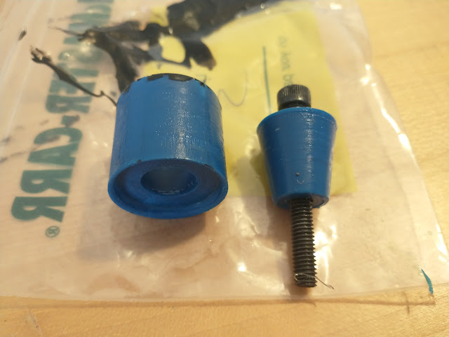
At the top of the mechanism, the screw is centered by a close-fitting Tivar HPV (extra slippery UHMW) bushing. 


At the top of the bushing, there's an end-of-travel bumper made from a square cross section o-ring.  This will take the edge off any impacts were the screw still has velocity at the end of travel.  The o-ring is glued to the bushing with some Loctite 380 Black Max


Here's the motor drive mount attached.  The motor drive mount is an HP MJF 3d-printed part.  At the center is a pair of bearings fan aluminum shaft with a tiny diametric magnet pressed into the end, for sensing the rotor position.  The spur gear in the motor drive mount meshes with the spur gear on the rotor, as seen two pictures down.


On the opposite side of the assembly from the guide bushing, there will be a set of guide rollers.  There are three rollers each that run in three axial grooves along the screw.  The axial grooves are shallow enough that they don't interfere with the spiral cam slots in the screw, and the 3 rollers per groove allow at least one of the rollers to always be engaged, even as the rollers pass over the cam slots.  

It's partially the fault of my job, and partially the fault of having a 5-axis mill at home, but all my parts are getting bad.  Below is the piece that holds the nine guide rollers.  It doesn't have any walls thicker than ~1.5mm, has holes bored from every which way, and has a bunch of weird undercuts.


Cross section of the guide rollers assembly.  The internal bosses visible in the picture above space the guide roller bearing inner races away from the walls of the part.  


Here's how the part fits up to the motor assembly.  The black ring at the end is another square o-ring bumper.  I still need to make the guide rollers.


And finally, here's a view of the assembly in its current state.  Just a few little parts left before it's ready for some testing - not jumping to start out, probably launching something of equivalent mass.  Either something's going to get launched very high, the mechanism is going to explode, or both, so it will be exciting regardless.


September 8, 2021

Closed Loop Espresso Part 2: Firmware Estimation and Control

I've made a lot of progress on the software and control side of the espresso machine, and learned some good lessons about designing the real version of the machine.

This is the first post in a series about the firmware/software, more to come soon.

To "spill the beans", as people at work say, here's a demo of the current state of the machine:


Here's what's going on while making the espresso in the video:
  • After the "Start" button is pressed, water is pumped through the heater and back into the tank at a constant flow rate, and the water/group heaters start heating.
  • Once both temperatures have converged to their setpoint, flow is switched from from the tank to the group.  At first, the water is flushed through the group to the drip tray, to purge air from the group.
  • Once the air is purged, the valve to the drip tray closes and "preinfusion" starts.  The group is filled up at a constant flow rate.
  • Once the desired shot pressure is reached (indicating the group is full and puck is saturated with water), the machine switches over to pressure control, and holds a constant pressure for the remainder of the shot.
  • Once the desired output weight is reached (for now estimated by integrating a pump displacement/leak model), flow to the group is controlled to zero and excess pressure is vented to the drip tray, so the drips through the puck stop quickly.
On to the subject of this post, firmware-level estimation and control

Flow Estimation
Originally I was planning on finding a flow sensor, but so far haven't found a sensor that's both affordable and any good - the impeller type sensors for all-in-one coffee machines have pretty terrible accuracy.  Fortunately I have enough instrumentation to estimate the flow pretty well.  Here's the basic model I'm using for flow estimation:


There's an "ideal" pump with constant displacement \(D\), spinning at angular velocity \(\dot{\theta}\), with the flow characteristic:

\[F_{ideal} = \dot{\theta} D\]

There's leak path between the outlet and inlet of the pump, with a nonlinear resistance which behaves quadratically.  The pressure, \(\Delta P\) across the resistor is:

\[\Delta P = C_{1}F_{leak} + C_{2}F_{leak}^{2}\]

Solving the quadratic equation:

\[F_{leak} = \frac{-C_{1} + \sqrt{C_{1}^{2} + 4C_{2}\Delta P}}{2 C_{2}}\]

\(\Delta P\) and \(\dot{\theta}\) are both measured, and the output flow is estimated by just adding up \(F_{ideal}\) and \(F_{leak}\).

This is (of course) in SI units, so \(\dot{\theta}\) is in cubic meters, \(D\) is in cubic meters per radian, \(\Delta P\) is in Pascals, and all the flows are in cubic meters per second.

Pump Characterization

The pump displacement is listed on the datasheet, and one could probably get a decent guess at the leak coefficients by squinting at the pressure/flow curves in the datasheet, but I measured these parameters in-place.

I measured the pump displacement by just pumping water into a cup on a scale, and measuring the weight in the cup vs pump angle.  Averaging over a minute of pumping, I got a result that was nearly identical to the datasheet value (hooray!).

I measured the leak coefficients \(C_{1}\) and \(C_{2}\) by blocking off the output of the pump with the needle valve, and varying the speed of the pump.  Blocking the output sets \(F_{leak} = F_{ideal}\), so the coefficients are found by fitting a curve to \(\Delta P\) vs \(\dot{\theta}\).

Looks pretty quadratic to me:

Flow Control

Flow control falls right out of the flow equations above.  Knowing \(\Delta P\) across the pump and have a desired flow rate \(F_{des}\), the desired pump velocity \(\dot{\theta}_{des}\) is set to:
\[\dot{\theta}_{des} = \frac{F_{des} + F_{leak}}{D}\]
Then the closed-loop velocity control is handled on the motor drive.  

Pressure Control

Pressure control was a bit more involved.  I started out by measuring the pressure frequency response of the system with the puck simulator installed and blocked off for zero flow, by applying a chirp torque signal and measuring the resulting pressure

The time series data can be turned into a bode plot by taking the ratios of the FFT's of the input and output.  I've fit a 2nd order model to it, which is what I'd expect with the output blocked - the dynamics should be dominated by the inertia of the pump motor and magnetic coupling, and the spring constant of the magnetic coupling + fluid.  When the output isn't blocked off, a third pole shows up, but that didn't matter too much for designing the controller.


I designed a pressure controller by loop shaping a PI + lead controller.  I was able to push it to ~90 rad/s (14.3 hz crossover) on the hardware before things got crunchy.


Here's the closed-loop step response (compared to the simulated step response given the 2nd order fit of the dynamics and the controller above).  There's a little periodic wiggle in the pressure (I think from the teeth of the gear pump), but overall it looks pretty good.


And here's the measured vs expected closed-loop frequency response, measured the same was as the open-loop frequency response with a chirp input:


Temperature Control

As boring as temperature control is, it turned out to be a real pain.  This prototype hardware (due to being thrown together out of mostly off-the-shelf sensors/fittings/etc) has the classic problem of non-collocated actuators and sensors.  Basically, the temperature sensors are relatively far away from the heaters, so there's significant dynamics between the heaters and sensors.  That, coupled with relatively slow time constants meant testing was very time consuming.  I frequently found myself filling up the water tank with ice cubes to cool things down faster.

There were a couple mildly interesting issues I ran into though.  One had to do with the SSR's I'm using to turn on and off the heating elements.  Typical SSR's only turn on and off at mains zero-crossings.  I just stuffed some PWM on the input to the SSR, in the hopes that the probability of the input to the SSR being high at the zero crossing would be equal to the PWM duty cycle.  Depending on the PWM frequency, this could work out.  But due to some timer constraints with the clock configuration for USB and CAN, my PWM frequency ended up evenly dividing into 60 Hz.  As a result, the PWM rising had a consistent alignment with the mains zero crossing, causing the SSR to turn on much more often than I expected given the PWM duty cycle.  Rather than trying to reconfigure the timers, I implemented software PWM so I could make the PWM period much larger than 1/60th of a second, to avoid this issue.

The other interesting issue I ran into had to do with my crappy hacked-together water heater design.  Here's a cartoon of (roughly) what happens in the water heater.  Water flows in at some inlet temperature, and out (hopefully) at the desired temperature.  Assuming the heater itself is a constant temperature, which is probably not an unreasonable assumption if it's highly thermally conductive, then the average water outlet temperature exponentially approaches the heater temperature throughout the heater.
  

Average is the key word.  As you can see from the cartoon plot, depending on the length of the heater and the convection coefficient between the heater wall and the water, the heater temperature could potentially be much higher than the outlet temperature.  And in reality, at a given cross section of the water flowing through the heater, the entire cross section will not be at the average temperature.  The water towards the walls of the heater will be hotter than the average, and the water in the middle of the cross section will be cooler than average.

For making espresso, the desired output temperature is typically somewhere in the low-90's C, which is awfully close to water's boiling temperature under ambient pressure.  The larger the difference between the heater temperature and the average outlet temperature, the larger the temperature gradient across the cross section of the water flow - so with a bad heater design (ahem) where the heater needs to be significantly hotter than the outlet, the water at the perimeter of the flow cross section can actually start boiling, even though the average water temperature is below boiling.  This results in the machine spluttering as it cycles water back to the tank while preheating, and introduces (highly compressible) steam into the group when the shot is happening, which affects the pressure control.

This issues seems solvable, and I think with a fresh heater and group design I can also significantly decrease the thermal mass and improve the temperature control bandwidth.  

This is getting long, so I'll pick up next time with a software post.

April 15, 2021

New motor drive firmware

 Over a year ago I started porting my motor control firmware away from mbed.  I've been working on it in spurts every few months and and ended up re-doing a lot of things from scratch, so it took much longer than I originally planned.  Find it here:

https://github.com/bgkatz/motorcontrol

The core motor control math hasn't changed (foc.c is nearly identical to the old version).  Lots of features have been improved though:

  • Encoder calibration/linearization is now current-mode, not voltage mode, and the calibration current can be configured from the serial terminal interface
  • Lots more parameters are configurable from the serial interface
  • Hardware setup is done with the Cube auto-generated setup code.  Linking between the hardware and motor control code is all done in hw_config.h so it should be pretty easy to port to different micros (someday I'll switch to using G4's instead of F446's....)
It's certainly not completely polished, but I think everything's working - I've been using this firmware for the espresso machine pump.  I don't have any Mini Cheetah hardware other than the motor drives any more, so I haven't been able to confirm backwards-compatibility.  Let me know if you try it and have problems.

February 25, 2021

Closed Loop Espresso Intro

Even before getting a lever espresso machine, I've been thinking about how I might design one if I were to do it from scratch.

This is the layout I've converged to:


The basic summary is:
- Electric motor driven pump pumps water through a heater.
- If the water at the output of the heater isn't up to temperature, the 3-way valve after the heater will cycle the water back through the tank.
- Once the water at the output of the heater is up to temperature, the valve switches and water is piped over to the group head and coffee.
- An extra "drain" valve between the group head and the drip tray relieves pressure after the shot is done.  Strictly this isn't necessary, but it serves a few purposes I'll get into later.

Critically with this setup, the whole tank of water doesn't have to get hot as it would in a boiler-based espresso machine.  I'm hoping to get the delay between powering the machine on and pulling the first shot down to a minute or less.  With a standard 15A mains outlet, it should be possible to real-time heat over 5 mL/s of water from room-temperature to espresso temperature, so main delay is in getting the thermal mass of the heater up to temperature.

The pump:

As far as I can tell, most "real" espresso machines use either vibratory pumps or rotary vane pumps.  From a pure performance perspective these don't seem like great solutions to me.  Vibratory pumps are noisy and hard to control (not saying you can't, Decent does pressure control with vibratory pump), and their main appeal is they're cheap and you can plug them straight into mains.  Rotary vane pumps are positive displacement (which is good for pressure control, roughly speaking), but tend to have large displacements - meaning for a given pressure, a lot of torque is needed at the input, since (ignoring losses) \(energy = torque*angle = pressure*displacement\).  Lots of torque = large motor or gear reduction.  However, the pumping power requirements for making espresso are tiny - on the order of a few watts of \(pressure*flow rate\) (9 Bar * 4 mL/s is 3.6 watts, and I think that's towards the upper end of espresso flow rates).  So a pump with a small displacement and a tiny motor (effectively getting "gear reduction" through the pump) makes more sense to me.  

Gear pumps were my first though.  What I wanted was "stainless steel body gear pump with PEEK gears", and it turns out that exactly this object exists and can be purchased on ebay for a few tens of dollars.  Even better, they all are magnetically coupled, so there are no shaft seals to leak.  A couple weeks later I had a Fluid-o-Tech MG304 pump.


Here's a shot of the inside.  The gears and bushings are CF-PEEK and the rest is stainless:


Here's a relevant plot from the datasheet.  The blue curve labeled "A" is for a 1 cP viscosity fluid, e.g. water.    Should be able to get over 200 psi at greater-than-espresso flow rates.  Since the pump displacement is so small, torques needed are in the ~.1 N-m or less range, which means I can use a tiny motor.


The main downside of gear pumps is leakage - which you can see in the pressure vs flow plot.  Gear pumps "seal" by having very close tolerances between the tooth tips and faces of the gears and the pump cavity, so some fluid leaks through these gaps.  For this pump it's very linear with pressure - at a constant input speed (which would be a constant flow if there were no leakage), output flow drops off linearly with pressure drop across the pump. 

The pump came with a low-end brushed maxon driving it.  I swapped that for a Moog BN23 Silencer motor I snagged from a Media Lab trash pile ~7 years ago.  One of its larger brethren was used to power the tiny lathe, and another by Dane for Robot Art.  A 3d-printed spacer adapts it to the pump.  Eventually this'll need to be replaced with a more temperature resistant part, since the water flowing through the pump will get fairly warm.

I modified a spare pendulum motor controller so I could plug in the pressure sensor.  Eventually I'll  have a separate micro for doing all the high-level control and use one of my usual motor drives with the built in encoder, but for now this was the easiest thing to hack together.  

This was my pressure control test bed -  the pump and motor, an automotive-style thread-in pressure sensor, a dial pressure gauge, and a needle valve as a variable load;


Testing closed-loop pressure control.  The pressure is plotted/setpoint set from the computer, and you can see the response to the needle valve opening and closing.  With this setup I can get around 10 Hz of closed-loop pressure bandwidth.


Some kind of interesting notes about the pressure control, looping back to the pressure relief valve.  One of the factors limiting the pressure control bandwidth is the compliance in the pump system.  A lot of this is from the magnetic coupling, which has a sinusoidal force-vs-displacement profile, with zero stiffness around zero displacement, and relatively low peak stiffness.  The other source of compliance is the fluid circuit - the bulk modulus of the fluid, the stiffness of the tubing and other stuff between the pump and the output, and much more importantly, the volume of air trapped in the system.  Without the relief valve, a big air bubble could get trapped in the top of the group head, above the puck of coffee, which would add a huge compliance.  To avoid this, the relief valve can be kept open until the group head is full of water, and then closed.

On to water heating:

The water heater is made from three 1/4" x 7" die heaters sandwiched between two thin aluminum plates, with a stainless tube snaking between the heaters.  My main goal was minimizing the thermal mass of the heater.  This design is kind of terrible, but it's functional enough to get me going.  The bend radius is super tight, and I did a few test bends that went well, but most of the bends in the final heater are awful.   Still, they didn't crack and still pass water, so good enough.


Two thick sheets of FR4 sandwich the whole assembly for insulation.  The machinist clamps are for extra pressure in the center.  Yeah, this design was bad.


For water temperature control, I have a platinum RTD in the flow of water, and a thermistor measuring the temperature of the heater.  I circulate water through the heating loop and back into the tank (in the picture above the metal pot...) until the the water temperature sensor has converged to the desired temperature, and then a 3-way valve is switch to pipe the hot water to the group head instead of back to the tank.  It takes around a minute to converge from room temperature to ~90C, and that's with a pretty terribly designed heater and a water temperature sensor with way too much thermal mass (I used a generic NPT threaded sensor so I could throw this together quickly).  So I think with some actual design I'll be able to get it even faster.

Similar to the heater, the group head was designed to be low thermal mass.  This is the opposite of how most espresso machines work, where the groups often have as much thermal mass as possible for "thermal stability"  But they're usually heated by water or steam from the boiler.  With the power of feedback control, low thermal mass, a group heater, and a group temperature sensor seems like the way to go.

I designed the group to work with a La Pavoni  portafilter, shower screen, and group seal, since I already had those lying around.  For the final version of all this (assuming there is a final version), I'll probably switch over to the standard 58mm portafilter size.

Here's the CAD and a cross section.  The typical wall thickness is 1.5-2mm.  I could definitely have gone harder with the light-weighting, but I wasn't in the mood for any analysis (this is pressurized to ~150 psi), so I just eyeballed it for now.  Next round of parts I'll probably be able to make it ~50% lighter. 


A screenshot of the CAM for making the top half of the group.  Thanks to the power of the 5-axis mill, it was only 2 setups, despite the holes pointed in every direction.


Video of the machining:


The finished parts assembled with seal and shower screen;


With the group head done, all it took was an afternoon of plumbing, sketchy wiring, and a tiny bit of firmware to read a few new temperature sensors and toggle valves.

Everything's just bolted to a strip of aluminum right now, and I stole the drip tray from the La Pavoni.


Here's the first test of the machine.  In my excitement I let it run for a little too long and the shot ended up over-extracted, but it turned out way better than I expected for a first try.  Pardon the wrench used as a handle for the group head - McMaster order with with a threaded handle was delayed.


For this test the group head wasn't heated, but I do have a 100W cartridge heater and thermistor for it, so the water flowing through it won't be cooled down.

While right now the machine is a huge heap on a benchtop, I think with some actual design it could be packaged to be very compact.