October 17, 2015

Ball Turner

I recently stumbled across a neat design for a ball turner on youtube, and ebay-rage-ordered all the parts to build one.


It consists of:

- A CXA (fits the MITERSlathe) boring bar holder with a 3/4" split bushing
- The cheapest 2" boring head I could find
- A 3/4" shank for the boring head

Total damage was ~$100.

I turned a couple 3/4" I.D. thrust bushings:


A handle:


The little radial-keyway allows the handle to be rotated 180 degrees and still have positive interference with the back of the boring head shank (which I filed a matching keyway into).


Threw together a quick carbide insert holder.  Someone else was on the mill, so all the shaping was done with a file, belt sander, and bench grinder:


Almost done.  The two set screws are used to tighten the play out of the split bushing:


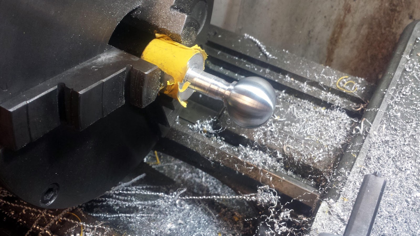
To test it out, I turned a ball for the end of the handle.  Success!


The ball was tapped, threaded onto the end of the handle, and locked with some red loctite:


Not bad for an afternoon.

September 7, 2015

Motor Mount and Bearing Shields

l spent way too long agonizing over how to mount the motor.  My basic requirements were:

  • Adjustable motor position for varying pulley sizes
  • Must only use one fastener to loosen the motor
  • Looks nice
  • Elegant, for some definition of elegant
To hold the motor, I made this piece which clamps around the motor housing (clamping bit not in this picture).  I didn't use the mounting holes on the face of the motor to leave more clearance around the pulley.  The ID was cut with a boring head, and the outside was roughed to an octagon, and hand-filed to round:


A steel square nut sits in a slot, so the motor position can be adjusted:


Here's the interesting part.  Rather than just bolting the motor through the slot, I cut a 45 degree counterbore in the plate that holds the motor, and a matching 45 degree brass washer.  When the bolt is tightened, the washer wedges the motor plate down into the aluminum plate below.  This way, the motor is firmly located against the metal both behind and below it.


I also made some simple bearing shields to hold the spindle oil in and stop chips from getting in the bearings. 


In the next episode I'll put the electronics together.

September 5, 2015

Tiny Tool Post

A tiny tool post for the tiny lathe.  The body of the tool post is 35 mm on each edge.  The standard tool holders  up to 3/8" lathe tools, and the boring bar holder is also for a 3/8" shank boring bar.


Brass wheels for setting the tool height were knurled on the MITERSlathe


A steel t-nut holds the tool post down to the compound slide.


Turning and boring tool holders:

August 27, 2015

Mini Lathe Pulleys

I'm back from the left coast, and for once I'm not busy building giant wooden contraptions for orientation.  Instead I'm trying to finish the tiny lathe before classes start.

I made some 2L sized v belt pulleys for the motor and spindle.  I considered using timing belts, but the spindle's going to be pretty high speed (>7k rpm max) and figured v belts would be a bit quieter.  Not to mention, v belt pulleys are much easier to machine.

The pulleys were cut turned using a grooving tool ground from a HSS blank:


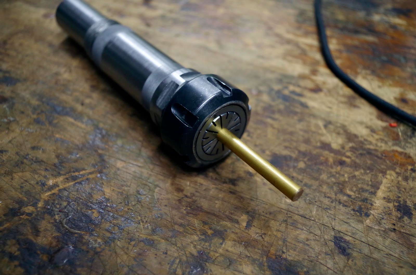
For the motor pulley, I had a lot of trouble getting a clean 9mm bore using the MITERS small boring bars, so I tried a technique seen here for making reamers.  I turned some 9.5mm semi-hardened steel shaft down to just under 9mm, and ground three facets in the end.  The faces were cleaned up on a whetstone, to debur the corners and get a sharp edge.  I drilled a slightly undersized hole, and expanded it to final diameter with the reamer.  The results was a pulley with a nice 8.99mm bore, which I tapped onto the motor shaft with a hammer.


Both pulleys are retained by set screws.  Normally I greatly prefer split collar style clamps to retain round things, but in this case it was hard to beat the compactness of set screws.  And it's dealing with fairly minimal torque compared to most things I build.  On the spindle side, the shaft diameter is fairly huge, which makes the force on the set screw smaller, and on the motor side, the pulley's press fit should deal with most of the torque.

On both the motor shaft and spindle I milled a little recess for the set screw to sit in:

Also notice the pair of lock rings for preloading the spindle bearings

And here's the spindle and motor pair:


Next up: Building a tiny quick change tool post.

June 7, 2015

Spindle and Headstock Machining

Machining the spindle turned out to be kind of a disaster, but I was mostly able to salvage things.

I started out with a chunk of crufted 1.625" steel round of an unknown alloy.  For whatever reason, I found it pretty much impossible to get a good surface finish on the stock with the MITERS carbide insert turning tools.  The only way I could get a finish resembling anything reasonable was to crank up the lathe's speed to the maximum and take really heavy cuts.  Unfortunately, this meant it was impossible to take finishing passes, so I screwed up the surfaces that mate with the inner spindle bearing races, and made them a little too small.  I did the final surface finishing using sand paper pressed against a precision ground steel block.  This seemed to fix the surface pretty nicely, but I was a little overzealous with sanding, and took off at least a thousandth too much off the front bearing interface, and a tiny bit too much off the back interface.

Since I didn't have an extra piece of steel to start over with, I attempted to salvage the spindle by using the newly acquired MITERS knurling tool to expand the shaft at the bearing interfaces.  It did work, although I lost a little concentricity in the process.  Fortunately, I can virtually eliminate the spindle's runout by taking a final pass off the critical surfaces on the mini-lathe itself.

Some design notes about the spindle:
- The front of the spindle is tapered and threaded to accept ER-32 collets.  I did the M40 x 1.5mm threading on one of the fancy Prototrak CNC lathes in the new N51 CNC shop.  This was a huge pain to set up.  All I wanted was a menu to input thread pitch/feed per revolution and a lever to engage/disengage the autofeed, but instead I had to actually program a job to do all the passes for me.  It took many hours poking through menus, reading the manual, and asking for help to finally figure it out.  Conclusion:  I should find MITERS a set of change gears for the Clausing lathe to approximate metric threading, so I can do my metric threading there.
-The spindle is extremely disproportionately large in diameter for a lathe of this size, and for good reason.  The bore through the spindle is .875" in diameter.  A stock taig spindle has a bore of just over .375", so this will be able to hold much longer large pieces of stock.


To put the hex at the front of the spindle, I grabbed a hexagonal 5C collet holder and fastened some scrap stock in it.  I then put the matching ER-32 collet and holder on the spindle, and tightened the two collets down face to face.  The vice stop made this a quick mill-and-rotate operation:


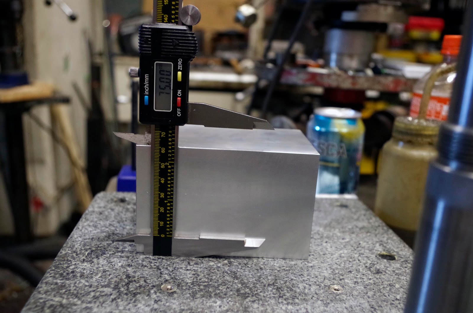
The headstock was machined from the wonderful 4"x4"x12" billet I scavenged last year.  I bandsawed off a 4.5" chunk, roughed it to size, and fly cut all the faces:


The quickest and most repeatable way I found to measure it was using a granite block scavenged from and old atomic force microscope, and those measuring surfaces on calipers that everyone seems to forget about.  By tramming the Bridgeport (a relatively rare occurrence at MITERS) and tapping down the block with a hammer every time I tightened the vice was able to get a thousandth or less variation between the corners on each face.


The headstock grips onto the dovetail bed.  I cut the slit for the clamping mechanism with the Epic Slitting Saw.  It made the poor Bridgeport's spindle sound extremely unhappy, but did a nice job.  Two counterbored M6 screws tighten down the dovetail to lock the headstock in place.


Bearing bores completed.  The tapped M4 holes are for a bearing shield on the front, and a motor mount on the back:


And here it is assembled with bearings.  Both the inner and outer races of the bearing are tightly pressed at the front.  At the back of the spindle, the outer race is a sliding fit held with retaining compound, and the inner race is a light press.  It should possible to disassemble without trashing the bearings by heating to loosen the retaining compound.


I have yet to machine the nuts that will thread onto the back of the spindle and preload the bearings with a disc spring washer.


And here the lathe updates come to an end, as I'm currently ~3,400 miles away from MITERS.

May 24, 2015

Mini Lathe Handwheels

The making of the handwheels involved a few revisions and many mistakes before producing something acceptable.

My first idea was to have a system vaguely like Bridgeport mill dials.  There would be a ring with scribed markings on it which could be rotated and locked down by another threaded ring.  Here's what the parts look like:  A simple aluminum handwheel, with a solid stainless steel handle press fit into it.  I really don't like the type with freely rotating handles - if there's any slop they feel cheap.


The ring which would later get scribe marks slips over the threads and rests against a lip at the back of the handwheel:


The threaded ring screws down to lock both rings in place, allowing you to set the zero on the dial:


This worked, but showed a major flaw when I actually attached it to the cross slide.  When I turn the dial, I tend to turn it by the cylindrical part of the handwheel, and only use the handle for extra support.  This means that when turning the dial counterclockwise, the threaded ring unscrews itself.

So that idea was binned.

I moved on to simpler solid handwheels.

These were turned from aluminum round, and like before, had stainless steel handles press fit in.  Each as 100 marks scribed around the perimeter, with every 10th mark longer.  With a 1mm pitch ballscrew, this gives 20 microns on the diameter per tick mark.

The handwheels are threaded onto the end of the ballscrews.  To to this, I cut a small section off one of the ballscrews, and used an angle grinder to cut slots into it, making a "ball tap" of sorts.

On the cross slide handwheel, I spaced out when scribing the marks, and made them on the wrong side of the handwheel.  I'll probably temporarily fix this by making a pointer that extends out to the tick marks, but eventually I'll just make a fresh handwheel:


I got the markings right on the compound though:


Ticks on the dial were scribed on the mill, using a single point cutter and indexing head to cut the marks.  The three jaw chuck on the MTIERS indexing head doesn't hold parts very centered, so I had to shim the jaws with paper to get the dial centered properly:


The 10 long marks were cut every 36 degrees, and short marks every 3.6 degrees:


The pinion that moves the carriage along the rack gear was crufted from an old stepper motor, and pressed onto an 8mm steel shaft with a shoulder turned in it:


Stock Taig lathes adjust pinion-rack clearance using an eccentric bronze bushing, but I wanted a pair of ball bearings supporting the pinion and carriage handle.  I machined a bearing holder and mating surface on the carriage casting:


The M6 screw that fixes down the bearing holder sits in a short slot, so that the pinion clearance can still be adjusted.

I made a carriage handwheel of similar style to the others.  It attaches using my go-to shaft collar style clamp.


And here's the lathe with all axes attached:


The carriage handwheel, unlike most lathes, has very little backlash: