January 28, 2014

A Tale of Two Robot Arms

The robot arm is now moving.  I started out by writing simple PID position controllers, and then making the motors do some fast back-and-forths.  Nothing is at all tuned right now, and I imagine my whole control loop will get fancier as I take 2.004 next term and learn how to actually do controls.

The basic control structure of the robot arm is this:  At the highest level, my computer runs some python code.  This code takes XY-space commands and does the inverse kinematics for the robot arm to convert XY to two joint angles, and then sends the joint angles over serial (using pySerial) to one of two mbed microcontrollers.  The mbed keeps one command to itself, and sends the other along to a second mbed over SPI.  Each mbed reads the encoder signals from the motors and uses that plus the commanded positions from my computer to do a PID control loop for each motor.  Finally, the mbed's send PWM and direction signals to a pair of Pololu motor drivers, which actually drive the motors.

For the sake of the robot arm and anything in its plane of motion, early testing was done without the arm attached.  Here's the linkage drive doing a 10 Hz shake:


And the arm's first link moving:


Once I got the core of my python code mostly working, I could send position commands from my computer:


Or so I thought.  Here, the arm was supposed to do a 1 Hz, 10 mm amplitude Y axis sine wave.  And it did, for a bit:


Somehow the arm managed to not crash into its physical limits, so nothing was damaged.  As far as I can tell, the problem was with my serial communication.  I added identification commands to the beginning and end of each block joint angles as a safety feature, so now the robot just stops when the commands go wrong, rather than freaking out as above.  Also, I'm now testing with the motor power supply at 5V rather than 20+, so the max speed and torque are much, much less dangerous.  After incident this I added an emergency stop button.


Which leads perfectly into the story of robot arm number 2.  The e-stop button and panel above came from the silicon wafer handling enclosure for a Stäubli RX60 robot arm.  A while ago MIT professor Seth Teller contacted MITERS looking for a home for this robot.  It turns out the robot arm was not just a robot arm.  It was actually a 100 lbs arm with a 200 lbs controller inside a 2,800 lbs box.  A very, very fancy box for inspecting silicon wafers.

Nancy, Peter and I went to retrieve the arm from its box, which was all stored at a storage warehouse just down the street.


And inside the box:


So shiny....  Everything was paneled in brushed stainless steel.  The e-stop panel I used can be seen in the middle left.


And the exciting part.  6 axes of robot-arm goodness:


Most of the important bits were Mikuvanned back to MITERS.  The robot was screwed to a table for temporary testing.


I pulled a couple of the panels off to see what sort of magic was on the inside:


Those are some fancy servos.  The two largest joints are driven by 200 V, 1 kW(!) servos.  That much power in an arm is kind of terrifying.  I couldn't tell what type of gear system was used, but excepting the rotation at the wrists, the joints are not backdriveable.

January 24, 2014

Fun With Encoders

Time to play with some microcontrollers!

For now I'm starting out using the mbed platform.  Think Arduino but faster and fancier.  I spent a lot of time using these in the lab over the summer, so that's what I'm using to get things up and running.  Eventually, I'd like to switch over to a BeagleBone Black, but there's a fairly large learning curve there that I'm not going to jump into just yet.

To sample the encoders, I first used the convenient QEI library.  Testing with this quickly showed me that one of the stock encoders was borked.  Upon opening it up, I could see a chip out of the encoder's glass optical disc.  Disassembling it revealed even more sadness on the surface of the disc.


Fortunately, I had a pile of fancy encoders scavenged from a lab cleanout over the summer, so I grabbed one of those.  The stock case and connector were extremely bulky, so I 3D-printed a new shell.

Stock:


Modified:


The new encoder is coupled to the motor by a timing belt from the motor's back shaft, and is held in place by some pieces of laser cut Delrin.


Adding this new encoder made another problem apparent.  The new encoder has 2,500 lines per revolution, over the stock encoder's 500, giving a resolution of 10,000 steps per revolution in quadrature mode.  The QEI software library just couldn't handle the pulse rate.  I could manually wave the robot arm around and get the microcontroller to lose track of the encoder's location

Fortunately, it turns out that the processor on the mbed has a built in hardware quadrature encoder interface.  However, on the mbed the pins corresponding to the interface are used up by indicator LEDs.  Some clever guy figured out how to use them anyway, by soldering wires to tiny pads on the bottom of the PCB, and wrote a driver as well.  Each board only has one such interface, so I'll need to use two of them to drive the motors.  To sync everything, they will eventually communicate with each other over SPI.    The hardware QEI seems to have solved the speed problem.  I can wave the arm around as fast as I want manually without it skipping a step.

I also assembled some boards to interface all the electronic components together.  From top left, clockwise are terminals for power supply and motors, a pair of motor drivers with added heatsinks, two mbeds, and two encoder breakouts.


Up next:  writing some kind of control loop so the robot can actually do things.

January 18, 2014

Now It Looks Like A Robot Arm

In the last month I've more or less finished the hardware side of the robot arm.  For the two fast axes, at least.  I'll deal with the z axis later.

Finishing the arm required a few big machining operations, especially for the elbow joint.  Naturally, I made these parts from big bricks of aluminum billet.  Elbow Part One started out as some 2" square billet, which I faced to size manually on the CNC mill, since the MITERS Bridgeport was temporarily out of commission.  On my first attempt at making this part, I discovered that when plunging into a pocket with a large endmill, the CNC mill's spindle stalls really easily.  Even with .5 mm plunges this occurred.  To resolve this, I manually drilled big pilot holes for the circular contours.  After the first CNC job, the part looked like this:


And after two more CNC jobs and one manual one, it was almost done.  It's a little sad that when you machine something this way 90% of the metal goes into waste chips.  But not nearly sad enough that I won't do it anyway.


I manually added the slot and tapped holes for a clamping mechanism.


When I ordered the pulleys for the belt reductions, I had a different design in mind for the plastic reduction than I ended up using.  In the final assembly, the output plastic pulley was torqued by the linkage it drove, causing it to deflect significantly.  To get a bit more precision, I got a nice aluminum pulley to replace it.  I drilled some big holes in it for moment of inertia reduction, and CNC milled plates for the linkage to attach to.


The second part of the elbow joint was machined manually out of some 2" round stock.


The driving link was made from some unidirectional carbon fiber tube I found lying around MITERS.  It is clamped at each end by a piece of aluminum that passes through the pairs of bearings on the pulley and elbow.  While turning the aluminum clamps, I found that the MITERS lathe turns a pretty significant taper.  To get a tight fit in both the bearings, I had to remove the taper by taking extra small passes off towards the chuck.


Hey, it looks like a robot arm now!  


For the time being I am going to ignore the z axis, and work on assembling the electronics and programming the thing, so that I can have something interesting and moving to display at TechFair.

December 29, 2013

More Snow Scootering

More messing around with the snow scooter outside of MITERS.  Now is just needs modular tank treads for the back to match the modular ski in the front.

December 16, 2013

Snow Scooter!

In the hours after MEETERS at MITERS, Dane and I came up with a ski attachment for our scooters, for the purpose of snowy scooter shenanigans.  Both our scooters have the same axle diameter, so switching it from scooter to scooter just takes adding a few shaft collars for spacing.


It was definitely a success.  Fast turns cause the back wheel to slip out, and at one point I accidentally turned too fast and did a 180 at speed.  Fortunately since the ground was covered in snow, it was a pretty soft landing.  The brake is pretty much useless, but you can stop quickly shifting your weight forward and going into a sideways slide, like you would on skis.


Credit for the last two photos to Billy Demaio

Belt Reduction #2 Finished

After another end of the week blitz on the CNC mill, I finished the second belt reduction.  The second differs from the first in that it supports the entire arm, while the first only drives a linkage to actuate the second link of the arm.

I started by pocketing the solid aluminum pulleys to make them lighter.  To get rid of any slop in the arm, the arm is supported by a pair of tapered roller bearings.


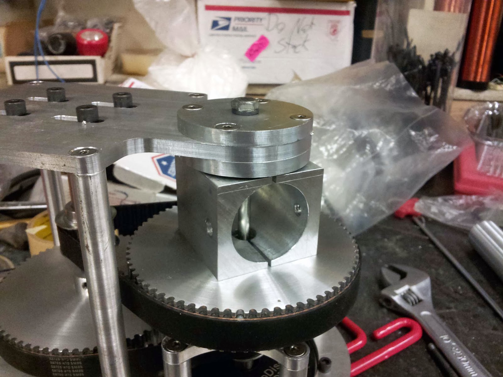
The arm, the first length of which for now is a thin-walled aluminum tube, is clamped in place with this aluminum block.  This arrangement allows the arm to be taken off the belt reduction by the removal of one bolt.  That way I can do the programming and control side of things without the arm in place.  This will stop the arm from self destructing by smashing into its physical limits.


A long bolt passes through the bearings, aluminum block, and pulley to preload the tapered roller bearings:


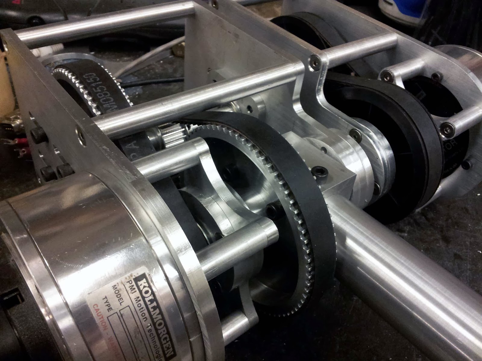
The two reductions will look roughly like this when assembled.  I still need to make the plates that connect the output pulley of the smaller reduction to a linkage.  Unfortunately, the 1/8" endmill I've been using to machine all these parts snapped 3/4 the way through making the first of those plates.


Next up is making the second link of the arm, as well as the linkage that actuates it.  More updates can be expected in early January.

In other news, Cambridge got snow this weekend.  SkiScooter pictures and videos will appear shortly.

November 30, 2013

CNC Everything

Just before last summer, a lab donated their old CNC mill to MITERS, in a mostly-not-working state.  Until now, I have not had a project that required any CNC machining, and even for this project I designed the parts for the belt drive reductions to be water jet cut, rather than CNC milled.  However, over this break my source for water jet access was out of town, so I decided to learn how to operate the MITERS CNC mill instead.

Here is one of the motor mounts, just after machining:


And here is a part in progress:


The parts look beautiful, with practically polished edges, compared to the extremely coarse edges left by an abrasive water jet.

so shiney
To make the standoffs, I used my old technique of making a clamping jig, so that I could face the ends off all the standoffs simultaneously.


Wherever possible I used countersunk stainless fasteners, for added shininess:


One great thing about CNC milling parts, rather than water jetting them is that I can make precise press fits for bearings without any fiddling with tool offset.  If I CAD my part with a hole .001" too small for the bearing, the mill machines a hole exactly that size.


And here's the assembled unit.  It is still missing the attachment for the linkage on the output 60 tooth pulley.