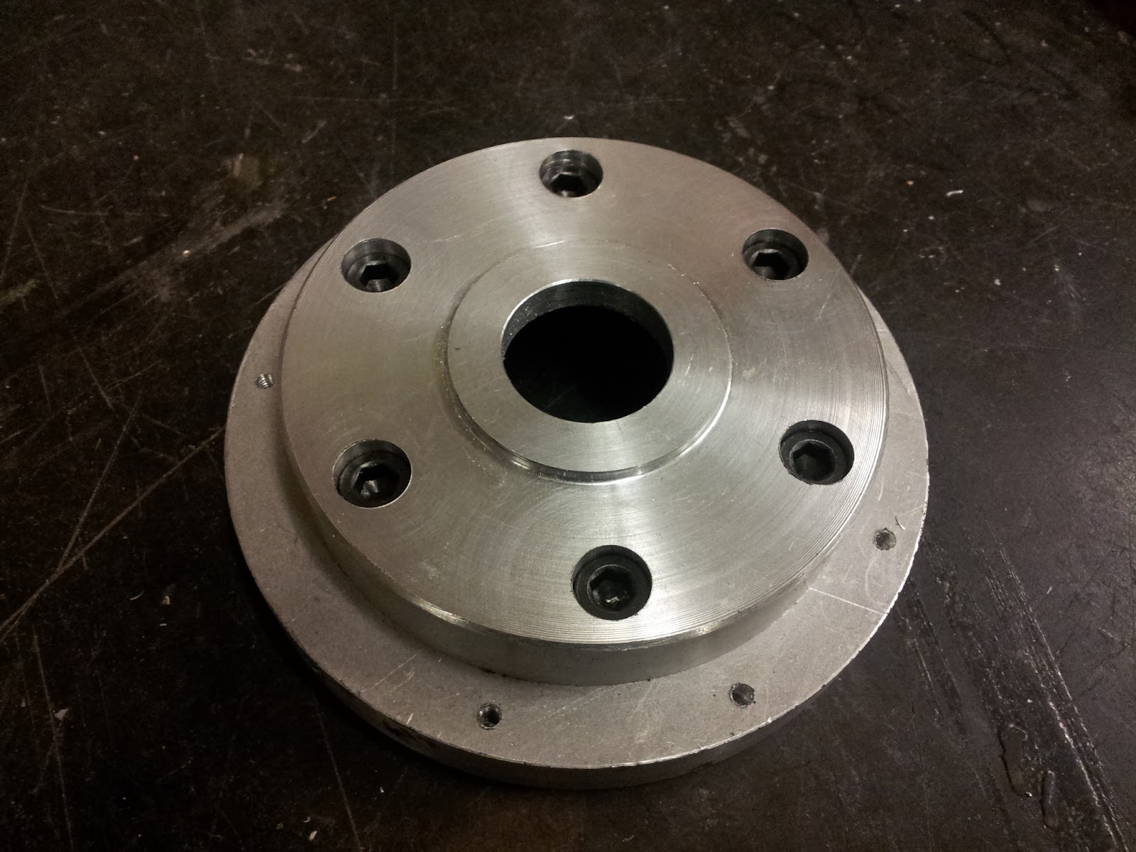
A new electric vehicle! More specifically, an electric tricycle. For lack of a better name, this project will temporarily be called the
Presently
Un
Named
Tricycle, which, as an acronym,
conveniently describes the time spent working on it. I came up with the idea for this vehicle a few months ago, while trying to figure out what to do with my Nice Project Fund courtesy of the
Instructables Fix and Improve it Contest. In an interesting coincidence, there seems to be a lot of simultaneous
tricycle building going on at MITERS right now, so when they're all finished I'll have some fun vehicles to race against.
The inspiration for the basic design comes from the classic
Radio Flyer kids tricycle, but, as I'm building it from scratch, rather than modifying an existing tricycle, my tricycle will have a number of improvements that should improve its riding characteristics, especially for people larger than toddler-size. The trike's most interesting features will include a pivoting front half, so that the rider can lean into turns as one would on a bicycle; rear wheel drive, through an eight-speed bicycle internal gear hub and differential; and a ~7 kW peak brushless RC motor. My original plans included even more cool mechanical bits, such as independent rear suspension with universal joint power transmission, but I realized I probably couldn't fit all those things into my target size.
Speaking of motors, the motor is the reason I started this project when I did.
Charles, who seems to have all the motors ever, was kind enough to give me a slightly-broken Turnigy 80-100, which will be powering the trike.
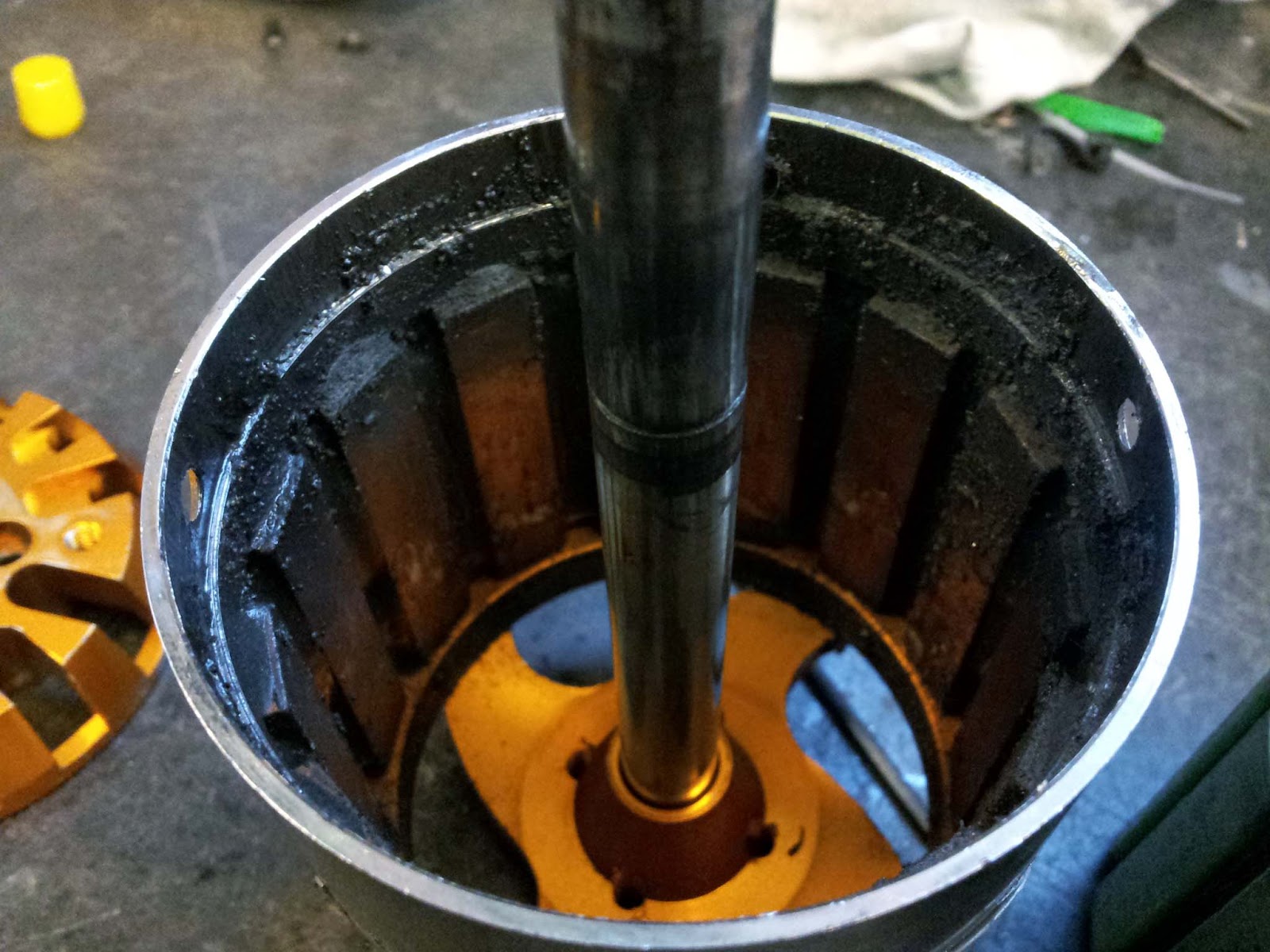
Fixing the motor turned out to be pretty simple, once I managed to get it open. The motor had more cogging torque than it should have, which apparently can be a sign of the windings being shorted to the stator/casing. I quickly confirmed this with some multimeter probing. Here's the inside of the motor:
The windings were shorted to aluminum body of the motor near where the wires exited. The hole through which the wires pass has fairly sharp corners, and the insulation around a bundle of wires had been damaged. To re-insulate it, I sanded down the corners to make them a bit rounder, heat-shrinked the exposed wires, and finally put a few layers of kapton tape between the bundle of wires and the metal. I repeated these steps on the other corner as well, so I wouldn't have to go back and fix it if it failed later on.
While I had the motor open, I took the opportunity to clean out all the grime that had collected on the inside:
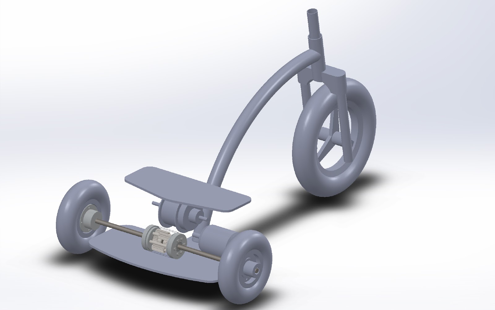
This project has been a great opportunity for me to learn a real CAD program (sorry Sketchup), so I've been modeling most of the trike in SolidWorks. Here are a couple shots of the basic design, missing plenty of parts like handelbars, a seat, and any kind of support for the drivetrain. Ignore the magically floating bits, they won't stay like that.
Lets zoom in on the differential, which has been ray-traced in Inventor for your viewing pleasure:
This differential has been a source of some internal debate for me. The design is heavily based off of the
spur gear differential found in
LOLrioKart and
CapKart, but shrunk down to about 2.5" diameter and fully enclosed (the shell isn't shown, so that you can see the inside). By the way, MIT, why do you use SolidWorks? I had to model pretty much the whole differential in Inventor, because it has a built-in gear generator. The cause for debate has been that I discovered a company called SAMAGAGA, that makes differentials for pedal-powered tricycles, that will sell me a
small differential for around half of what it would cost me to build the differential pictured above. Additionally, the SAMAGAGA differential uses nice things like helical bevel gears, which I can't get on McMaster, which would make it quieter than one with straight-cut gears. It does come with annoying splined sockets for the output shafts, but that's a fairly small drawback compared to the package as a whole. So why wouldn't I just buy the differential? If the sole purpose of the project was the end product - a fun, interesting vehicle to tool around in and maybe
race on occasion, then I would just buy the differential. But the end product, in my opinion, is only a small part of the project as a whole, and building a differential from scratch is a pretty awesome project in and of itself. I would get far more entertainment and learn way more from building it myself that I would from just buying an assembled part. Plus, if I were truly concerned about about ease/cost/practicality over build-process/acquiring skills and knowledge/fun , my website would be pretty empty.
tl;dr: I like building things. I'm going to build my own differential
Another piece of the drivetrain puzzle is the internal gear hub. For those that don't know, an IGH is a hub meant to be laced into the rear wheel of a bicycle, and contains a fully enclosed and sealed multi-speed planetary gearset. They are designed as a maintenance free alternative to the conventional derailleur system, and are made in varieties ranging from 2-
14 speeds. The particular IGH I will be using is
this one, made by Shimano, which will provide a total gear range of 307%. Why use a multi-speed drivetrain in an electric vehicle? After all, even Tesla's cars are one-speed. Electric motors, like internal combustion engines, have an RPM range over which they produce their maximum power - in permanent magnet motors, this should ideally happen at 1/2 no load RPM and 1/2 stall torque. By having multiple gear ratios between the motor and the wheels, the motor can be kept in its maximum power range (or efficiency range, if you're that way inclined) for longer, meaning better acceleration for a given top speed, at the sacrifice of increased cost and mechanical complexity. Because I thought it would be interesting, I made some pretty graphs to demonstrate.
For a permanent magnet motor, the motor's torque (or current) vs rpm curve looks like a straight line between maximum torque at 0 rpm, and 0 torque at maximum rpm. The following graph shows torque vs wheel rpm for all the gear ratios available on the IGH I'm using. In an ideal situation, one would shift to a higher gear once the torque in that gear at a given wheel RPM becomes greater than the torque of the lower gear. These points are indicated by vertical dashed lines. With perfect shifting, your wheel-torque vs wheel-rpm would follow the top of the curve.
Similarly, here's what the power vs RPM curve looks like:
For the particular motor I'm using, however, these charts are not very realistic approximations. The 80-100 will happily suck down hundreds of amps near stall, but I most likely won't have a controller that can handle that much current (at this point, I'm thinking mini Kelly KBS). Current limiting will make the negatively sloped torque vs rpm curves shown above become horizontal (since torque is proportional to current), until the motor's current draw is less than the controller's limit, at which point the curve resumes it's original shape. Limiting to 1/2 and 1/3 respectively the motor's stall current would look something like this:
And power:
Maybe when I learn how to do math I'll turn these into velocity vs time graphs, so I can more directly compare the performance of single vs multiple gear configurations. Presently, my results (not shown) make sense for the 1:1 ratio, but get messed up by those pesky constants from the gear ratios. Still, these charts get the basic point across.
Enough of pretty charts and my musings, and on to actually building things.
As an exercise in planning, I tried to make myself CAD the whole thing before actually jumping in and building anything, but that didn't happen. Basically, there are plenty of parts of the trike that either aren't critical enough or I understand well enough to not need CADing, so I took some breaks from designing to actually build some things.
The fist thing I built was the was the trike's fork. Repeating my strategy from my
last EV, I started out with a crufty old mountain bike fork. I removed the lower half of the fork, as well as the springs and dampers, to leave the steerer, crown and significantly shortened legs.
Removing the suspension parts left ugly threaded voids in the tops of the tubes, so I turned some press-fit caps to fill them.
The bits of the fork that actually hold the front wheel will be machined out of aluminum and clamp onto the fork legs.
From MITERS' box of bicycle headset parts I was able to find bearing cups and bearings for a 1 1/8" steerer. The head tube was made from some thick steel tubing, which had previously been welded to three other tubes, and I had to free with generous use of the sawzall and angle grinder. The outer and inner diameters were turned down to the appropriate sizes, and the bearing cups were pressed in with a mill vice. I couldn't find a 1 1/8" crown race, so I turned one out of aluminum. This wouldn't have worked if I had been using loose bearings, but I was able to find some sealed headset bearings, so they won't wear down the soft aluminum.
Since the headset is threadless, the fork and bearings are constrained by the stem, which clamps onto the top of the steerer tube. I milled the stem out of a random large aluminum block I found. Here's the head tube, fork, stem, and headset assembled:
When I decided to have a curved frame, I figured I would have to buy some tubing and find a proper tubing bender somewhere on campus. Fortunately I didn't go out and do that, and instead spent my time poking around the corners of MITERS. By some extraordinary luck, I found two lengths of curved steel tubing of nearly the exact same diameter and curve radius as I designed into my CAD model. Here's a crude 2D projection of the trike frame with the tube on the floor:
To join the curved tube to the headtube, I first mitered the tube on the mill using a hole saw:
I then MIG welded the two parts together. My aesthetically unpleasing welds were cleaned up with an angle grinder:
There happened to be a perfect pair of handelbars for the trike attached to an old stripped down scooter frame. Unfortunately it was welded in place, so I had to cut it off and do even more angle grinding get rid of all the added metal. I made a 4 bolt clamp in the front face of the stem, to hold the handlebars:
The ugly hex bolts will be replaced by socket cap screws, once I get a hold of some long enough.
To make the frame's pivot point, I scavenged some 7" x 3/4" precision shafting and some matching bushings, and made two bushing blocks, which will be bolted underneath the bottom plate of the rear wheel and drivetrain assembly. The protruding end of the shaft will be fixed to the part of the curved tube that touches the ground in the picture above, with some sort of clamp I haven't yet designed:
That's all for now. More to come soon.