May 24, 2015

Mini Lathe Handwheels

The making of the handwheels involved a few revisions and many mistakes before producing something acceptable.

My first idea was to have a system vaguely like Bridgeport mill dials.  There would be a ring with scribed markings on it which could be rotated and locked down by another threaded ring.  Here's what the parts look like:  A simple aluminum handwheel, with a solid stainless steel handle press fit into it.  I really don't like the type with freely rotating handles - if there's any slop they feel cheap.


The ring which would later get scribe marks slips over the threads and rests against a lip at the back of the handwheel:


The threaded ring screws down to lock both rings in place, allowing you to set the zero on the dial:


This worked, but showed a major flaw when I actually attached it to the cross slide.  When I turn the dial, I tend to turn it by the cylindrical part of the handwheel, and only use the handle for extra support.  This means that when turning the dial counterclockwise, the threaded ring unscrews itself.

So that idea was binned.

I moved on to simpler solid handwheels.

These were turned from aluminum round, and like before, had stainless steel handles press fit in.  Each as 100 marks scribed around the perimeter, with every 10th mark longer.  With a 1mm pitch ballscrew, this gives 20 microns on the diameter per tick mark.

The handwheels are threaded onto the end of the ballscrews.  To to this, I cut a small section off one of the ballscrews, and used an angle grinder to cut slots into it, making a "ball tap" of sorts.

On the cross slide handwheel, I spaced out when scribing the marks, and made them on the wrong side of the handwheel.  I'll probably temporarily fix this by making a pointer that extends out to the tick marks, but eventually I'll just make a fresh handwheel:


I got the markings right on the compound though:


Ticks on the dial were scribed on the mill, using a single point cutter and indexing head to cut the marks.  The three jaw chuck on the MTIERS indexing head doesn't hold parts very centered, so I had to shim the jaws with paper to get the dial centered properly:


The 10 long marks were cut every 36 degrees, and short marks every 3.6 degrees:


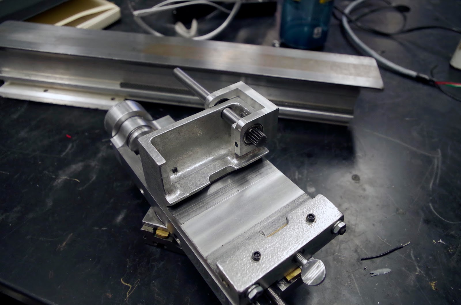
The pinion that moves the carriage along the rack gear was crufted from an old stepper motor, and pressed onto an 8mm steel shaft with a shoulder turned in it:


Stock Taig lathes adjust pinion-rack clearance using an eccentric bronze bushing, but I wanted a pair of ball bearings supporting the pinion and carriage handle.  I machined a bearing holder and mating surface on the carriage casting:


The M6 screw that fixes down the bearing holder sits in a short slot, so that the pinion clearance can still be adjusted.

I made a carriage handwheel of similar style to the others.  It attaches using my go-to shaft collar style clamp.


And here's the lathe with all axes attached:


The carriage handwheel, unlike most lathes, has very little backlash:

May 20, 2015

Cutting a Rack Gear on a Bridgeport

I considered buying a little metric rack gear for the lathe on SDP-SI, but it would have cost around $30.  Instead, I figured out how to machine one on the MITERS Bridgeport.  

The basic idea, which came from a thread on a machining forum which I can no longer seem to find, is this:  Put a single-point cutter in a fly cutter.  Angle the head of the mill such that the cutter points straight down.  Cut a tooth, then feed by the  pitch of the rack.  The forum-poster thought it would create a slightly incorrect tooth, because of the angle of the fly cutter.

Turns out, though, if the mill is angled between 90 degrees  and 90 minus the pressure angle of the gear, the teeth actually come out perfectly shaped.  Here's why:

This is what a single point cutter looks like when it has been swept around the axis of the mill spindle.  In this case, the mill is angled to 65 degrees, and the cutter is for a 20 degree pressure angle rack. 


The tooth profile that would be cut in this configuration is shown below.  Since the mill is angled to 25 degrees from horizontal, but the pressure angle is 20 degrees, the cutter removes an extra 5 degrees from one side of each tooth.  Simply rotating the head of the mill to between 70 degrees and 90 degrees means that the plane the tip of the cutter moves in doesn't actually interfere with the shape of the tooth being cut.  The result is a normal tooth shape, despite the funny arc the cutter moves in.


Here's what it looks like in practice:


I machined a .1" pitch rack out of some aluminum to make sure the process worked:


On to the actual rack, which is approximately a .5 module metric pitch.  The cutter was ground from a small brazed carbide lathe tool.  The rack was machined in three passes, to avoid loading the tool too much.  This took a very, very long time.


But I'm quite pleased with the results.  The rack feels like it meshes quite nicely with a (presumably) .5 module gear pulled off an old stepper motor.


Coming soon, making shiny hand wheels, and machining the spindle and headstock.

May 19, 2015

Compound Slide

School's over, so it's time to catch up on documentation.  The lathe isn't finished yet, but I've made a lot of progress.  Sadly, I won't have shop access this summer, so the lathe won't get finished until August or September.

The compound was made from two pieces, a dovetail slide which holds the ball nut, and a cone-shaped base.  The two pieces were silver-soldered together.


The base of the slide had a ring milled in it with a rotary table, so that the force clamping it down to the cross slide acts at a maximal radius:


The cone is clamped pulled down by a pair of set screws, the ends of which are turned to 45 degree cones:


The carriage, compound, and cross slide assembled on the bed of the lathe:


May 4, 2015

Cross Slide, Take 2

Man am I behind on documenting the mini lathe.

My original plan for the cross slide was to anodize it like Taig does, to prevent wear and galling on the aluminum-aluminum interface.  I decided instead of dealing with nasty chemicals and temperature control (required for hard anodizing), to just remake the part out of steel.  Steel machines much more slowly, but since I had already machined the part once, it went reasonably quickly.

Fortunately, Nick had a big chunk of steel which was very close to the size I needed:


The block was milled to size and top and bottom surfaces fly cut:


I forgot to take more pictures of it, but it looks pretty much identical to the original aluminum one.

I also attached one of the ballscrews to the carriage:


Bearing holders for the ballscrew were milled on the MITERS CNC mill.  The ballscrew is retained radially by a single ball bearing, and axially by a pair of needle thrust bearings (not shown here):


Prepare yourself for the making the compound slide and machining a rack gear on a bridgeport in upcoming episodes of Tiny Lathe.