This term I took
2.007 Design and Manufacturing 1. The class centers around a robotics competition. In fact, this class is the mother of all robot competitions, spawning FIRST and its derivatives (
more 2.007 history here). Technically since I am Course 2A (MIT's more flexible version of mechanical engineering) rather than Course 2, I was not required to take this class, but I haven't really done a robotics competition since highschool, and I didn't want to pass up the chance to get to build robots for credit.
This year's competition,
MITSKI, was an Alpine skiing course. The playing field consisted of two ski slopes, each of which had three different grades: a 15 degree "bunny slope", a 45 degree "cruising run", and a 60 degree "black diamond slope". Robots could get points for going up each of these slopes. Each slope was also divided into two sections down the length, by a line of trees. One of these sections was the "ascend region", and was reserved for going up the hill, and the other was the "ski area", where robots could go down the slopes.
Those were the features of the game that mattered for my strategy, but the playing field had lots of other features as well, like slalom flags, medals, and a score multiplier.
Full rules can be found here.
Here's the 2.007 parts kit:
It includes a few thicknesses of steel and aluminum sheet metal, a plywood sheet, some ABS sheet, a few servos, a few gearmotors, square and rectangular aluminum tube extrusions, hex shafts, some chunks of delrin and nylon, and an assortment of other goodies. Although we generally were required to stick to these materials, they did allow some substitutions (such as acrylic for the ABS, for ease of laser cutting), and additions. I managed to incorporate some nice machined chunks of aluminum into my parts without anyone caring.
In terms of electronics, you could do pretty much whatever you wanted. The class provided you with an arduino nano and a carrier board to go with it, and a little 500 mAh 2S LiPo battery, but you could bring in other electronics if you wanted to. However, total energy stored by your system (be it in the form of batteries or mechanical energy storage) was limited to 30 kJ.
Robots mean motors. 2.007 provides you with a wide (but strictly limited, no bringing your own motors or using 10 of their biggest ones) selection of motors to use.
The workhorse motor of 2.007 is the BO-P5 planetary gearmotor. It's a cute little 3V DC motor with 40:1 planetary gearbox. There's also a version with a 120:1 gearbox. These things are rated for around 3W peak at 3V. They seem perfectly happy to run straight off the 7.4 volts from a 2S LiPo though (although the 2.007 staff frown upon this practice, preferring you to power them off the 5V regulator on the provided arduino carrier board).
After messing around with servo ants for the first week or two, I started working on a game strategy. I decided pretty early on that repeatedly climbing the hills would probably the most consistent way to score lots of points. I spent a lot of time digging into the rules and asking the course instructors very specific questions about rules to figure out exactly what the limits of what I could do were.
My final strategy hinged around two features of the rules:
1. Ski Lift: You are allowed to build a mechanism to assist your robot in ascending the hill. It can be preinstalled on the playing field, but can only touch the playing field at three specific mounting points, and cannot extend into the robot's starting box.
2. Multiple Robots: You can build multiple robots. Robot is roughly defined as something with independent control and actuation. To score points, a robot has to take action towards scoring.
Adding those to things together you get this strategy:
- Build lots of tiny robots
- Build a really fast ski lift that can bring the robots both up and down the hills
- Make the tiny robots grab onto the ski lift at the beginning of the match
- Turn on ski lift, carry lots of robots at a time up and down the hills until the end of the match
Rough calculations for points scored:
- 70 points for going up all three hills
- 2x autonomous bonus during first 30 seconds
- ~1 m/s ski lift speed
- ~8 m combined distance up and down the hill
- 3 laps completed during autonomous period, 11 more during manual control period.
- 3*70*2*n + 11*70*n points scored for n tiny robots = 4760 points for 4, 7140 for 6
Here are some mini-robots to ride the ski lift:
The mini-'bots consist of a servo, a 3D-printed frame and claw, an ATTiny85, a photoresistor, and a little LiPo battery. We were allowed to use up to 6 cubic inches of 3d printed material for the competition, so I made good use of that restriction. These parts were all printed on my Up! rather than the lab's fancy Stratasys printer, for convenience.
To make them compact, there's a right-angle bevel gear drive between the servo and gripper. Also each of the grippers has a little latch at the end, to help prevent them from opening up accidentally during the competition.
Here are the controllers for the mini-robots. Each has an ATTiny85, a 7805 voltage regulator, a photo resistor for sensing the start signal, and a diode to prevent me from exploding everything by plugging the battery in backwards. Hat tip to
Charles's 2.007 experience for encouraging me to add the reverse protection diode. It definitely saved these boards on multiple occasions.
The playing field has one white LED that turns on to start the match. To distribute the start signal to four little robots, I made another device that sensed the one LED and then turned on a strip of LEDs to enable the mini-'bots:
The whole system working looks like this:
On to the ski lift. First thing I did for the the lift was design and build a giant 4-motor gearbox to combine all the motors I had left to use after building the mini-bots. This consisted of 2 of the BO-P6 motors and 2 Vigor VS-10 servos. In all its ray-traced glory, it looks like this:
In actually building this thing I took a few tricks from
AndyMark (who also make gearboxes combining mis-matched motors). Namely, torque is transmitted through hex shafts everywhere. To make hex bores in all the gears I could have used the fancy broach in MIT's Pappalardo Lab, but they are only open during "real person hours" (7:30 pm to 5:00 pm, or something like that), so as usual I opted to build everything at
MITERS. So my method for making for making the hex bores was infinitely sketchier than using a broach. I first chucked the nylon gears into the lathe, and chucked a piece of aluminum hex shaft into the tailstock. Then I whipped out a propane torch:
I heated up the shaft to above nylon-melting temperature, and then crammed the hot piece of metal straight through the gear. The plastic that oozed out was easily cut off afterwards, and the resulting fit was excellent.
Some amount of laser cutting and 3D-printing later I had a sweet gearbox:
At this point I got distracted by my four other classes and failed to make any significant progress for a few weeks.
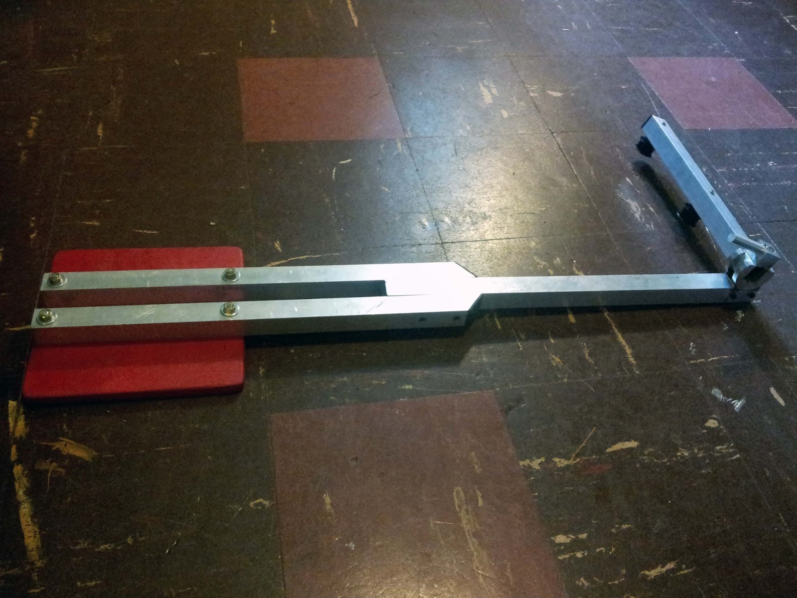
Then I started making some really silly parts for the ski lift.
I wanted it to be very adjustable, so I could tune it to the playing field. To adjust the angle of the idler pulleys at the bottom of the lift, I made this device. The piece on the left is a section of a cylinder with a dovetail cut out arounds its circumference. A nut fits in this dovetail. The cylinder mates with the cylindrical cutout on the piece to the left. When the bolt is tightened, it locks the cylinder down into the cutout at whatever arbitrary angle you set it to.
With the handle on top, I could remove the idler pulley assembly and switch it to the opposite side in just a couple seconds, if I needed to reconfigure the lift for the opposite side of the playing field.
For making the handle, I tried out a neat machining trick to machine a cylindrical handle into square stock, using a mill. This could have been done with a four jaw chuck on a lathe, but instead I used a boring head with the cutting tool turned backwards. Normally this tool is used for boring large precise holes through stock, but if you flip the cutter around it can cut cylinders.
Like this.
The red pad is where the bottom half of the lift assembly bolts to the playing field:
The top half of the lift got even more ridiculous. The lift's supporting tower was made from a foot of 3"x1" hollow aluminum extrusion. I made a big clamping mechanism through the top of it. I got into a shiny knob making phase for this and a few other random projects, so I made another shiny handle to adjust the clamp.
Turning the arc in the handle was an interesting experiment. To do this I loosened the lathe's toolholder on the toolpost, so that it could rotate freely. I then clamped a huge C-clamp to the toolholder, as a handle. I then manually rotated the tool into my spinning part, so that it cut an arc. As long as I took very shallow passes, it made a very smooth cut.
This piece fits into the clamping mechanism. It holds a 1" square piece of aluminum tubing, with a threaded rod through the center.
The assembled tube-and-threaded-rod part. The nut on top is cranked down into the square cap I machined for the tube, clamping the tube into the cylindrical base.
The clamp can be used to easily adjust the angle of the protruding tube, so that the lift can be easily switched between left and right sides of the playing field.
Next came a gearbox attachment. It was also adjustable, of course.
I laser cut a big timing belt pulley to mate with the gearbox's hex shaft output.
The assembled top half of the lift:

Somehow I never got a picture of the entire setup attached to the ski slope. At this point it was Thursday morning, and the next day was robot impound. Despite my combing of the rules, there was one rule at the end of the list I missed until about a week before impound: Ski lift devices were not allowed to extend into the ski-slope area of the playing field. They had to stay completely within the ascend region. This meant that to do multiple laps with my mini-robots, they had to extend over the line of trees on the way down the hill. To do so, they could not be centered under the timing belt that ran around the ski lift. My strategy for balancing them was to add a counterweight to the opposite side of the belt where the robots attached. Unfortunately, this turned out to be fairly disastrous. On the way around corners and up the hill, the robots were completely out of control, and would bang into pretty much everything possible on the way around the lift. This resulted in them flying off the lift and things generally being terrible.
At this point I was faced with a hard decision: I could either spend the rest of the day in Pappalardo until 5:00 pm trying to get the lift to work as I intended, or I could spend the rest of the day and night at MITERS building a robot to carry my mini-'bots, and still impound on Friday morning. I decided I probably would not be able to get the lift working as I wanted within the shop's open hours, so I chose the second option.
In retrospect, I regret this decision. A third option would have been to give up on doing multiple laps with the ski-lift, and just have it carry my robots to the top of the hill once during the autonomous period. This way, I would not have had to cantilever the mini-robots off the lift's timing belt, which would have eliminated all the problems with the lift. Even just one ascent with six mini-robots would have scored me 840 points every match. This would almost certainly have been enough win the competition. One robot in the competition broke this score, but it only did so once out of its five matches.
Anyway, I went to MITERS and blitzed a robot to carry my other robots:
Wheel assemblies. The servo wheels are bolted to laser cut hex-bored hubs, and have aluminum hex axles which pass through nylon bushings in the aluminum frame.
I printed some motor mounts which I later had to machine down because I designed them to be too thick. If you look carefully here, you can see that the motors are not actually bolted to anything. When I turned the axles, I didn't have quite the right bit size for the motor shafts, so the axles ended up being slightly non-concentric with the motors. To stop the motors and shafts from being overconstrained and binding, I "floated" the motors. They can't rotate, but are somewhat free to jiggle around as the wheels turn.
The mini-'bots hold on like this:
I spent the Friday morning of impound getting my autonomous mode working. I was able to get it to drive up the first two slopes with the four mini-'bots, for a solid 200 autonomous points. Manually driving, I was able to score up to another 425 points on my best run, for a total of 625. Not nearly as good as the lift would have been, but in a similar range to the other top performing robots from the class.
Impound happened. In my seeding run I scored 472 points. One of the mini-bots lost power and fell off after the autonomous lap, and I lost another after my first manual lap due to poor driving and crashing into things. From lots of testing, I also found that my robot didn't like to be started on the left hand side of the playing field. For some unknown reason, it would often decide to suddenly take a sharp right and drive straight into the trees part way up the hill. It never had this problem on the right sides of the playing field. This was despite including a massive compensation overspinning the outer wheel, in an attempt to make the robot hug the wall.
On to the competition. People who scored high early on in the semester could place out of the preliminary rounds. I was not nearly that on top of things, so I had a play-in round the day before the finals. There were around 60 play in matches, and to qualify for the finals, you had to both win your match and get one of the top 16 scores. My play-in round didn't go as smoothly as it could have, but I still scored 300-something points and qualified for the finals.
Finals day. I was the 11th match of the night, so I showed up at 7:00 pm, right as things were supposed to get started. I turned on my robot, and was greeted with that burning electronics smell as one of my VEX 29 motor controllers decided it was done with life. Fortunately the 2.007 staff had brought lots of tools and spare parts, so I was able to replace the motor controller with 5 or 10 minutes to spare before my match.
My first round went pretty well. I did lose one mini-'bot, but scored 414 points and actually got the highest score of the entire first round of matches. Things went downhill from here. During my next round, I started on the left side and my robot crashed into the trees during the autonomous period. Fortunately the situation was salvageable, and I managed to score 200-something manually and scrape a win. Things got much worse in the round of 8. Again I started on the left. My robot made it up the first hill fine, but then took a spontaneous right, drove through a gap in the trees, and crashed into more trees and rocks at the center of the field. I was unable to recover from the tangled wreck of mini-bots and trees, and ended up only scoring 30 points.
So I was out. I guess I learned something about doing things ahead of time and testing them, rather than just assuming they will work. Also thinking through emergency decisions a bit more. I could have kept the lift and done significantly better in the competition than I realized when I decided to abandon it.
Anyway, here's some absurd aluminum billet I've scavenged over the last week that will serve as consolation:


