December 28, 2020

New Photo and Video Feed

 You'll now notice that I added a Feed tab to the top of the page.

When I started the blog, I would wait until I completely finished a project, then do one gigantic writeup at the end.  This habit was left over from when I used Instructables to document things.  As my projects got more complicated, that blogging style stopped working.   So I started the In-Progress section for shorter technical updates. When I (on occasion) finish something, I now throw a summary on the main page, and links to the relevant posts from the in-progress section.  I think this has been working fine, but I still tend to hold onto stuff until I've made enough progress for a proper technical blog post.  

Despite the relative infrequency at which I write detailed posts, I think most weeks I do something side-project related that someone on the internet would find interesting.  To avoid cluttering the proper blog, I made a new Feed section where I plan on just throwing up images or videos with one or two sentence descriptions.  "Hey, that sounds like Instagram", you might say, and you'd be right.  But I've avoided Facebook and Instagram this long, so I don't intend to stop now.  Maybe I'll get bored of this and it will fall by the wayside, but for now, enjoy.

December 9, 2020

La Pavoni Europiccola Lever Espresso Machine Restoration

I've had a La Pavoni Professional lever espresso machine for a couple years now, which I got on ebay and fixed up.  Getting it working turned out to be completely uneventful, so I never wrote up anything about it.  I recently restored a Europiccola for my sister, and this time around the restoration was much more involved.  It was in pretty rough shape when I got it - all the seals were shot, the sightglass was smashed, and the copper/brass plating was  peeling horribly.  But the heating element and electronics were in good shape, and core mechanical pieces worked.

I forgot to fully document the state I received it in, but here's what it looked like minus the grouphead:


All the seals needed replacing.  The trickiest of these was the seal in the top of the grouphead.  This seal is held in by a brass washer and a retaining retaining ring, which was made out of non-stainless steel.  It sits in a chamber full of steam, so I don't know what they were thinking there.  So the retaining ring was extremely rusted, so much so that the holes used for removing it with snap ring pliers were gone:


I was able to slowly chisel it loose and pry it out with a dental pick.  This is what was left of the original retaining ring (left), seal, and washer:


Here it is after installing a new seal, cleaning up the brass washer, and using a new stainless retaining ring.  Sorry for the blurry pictures:


This machine originally had a copper finish on the boiler and gold/brass finish on the grouphead and base, but both were discolored and peeling.  The finish on this  unit was strange -  on the outside, there was a clear varnish layer (the source of the peeling).  Under that, the boiler has an electroplated layer of actual copper, and the base has an electroplated brass layer.  Neither of those layers were in very good shape.  Where the copper/brass were wearing through, there were signs of a chrome coat beneath that. 

I took the boiler as far apart as I could before stripping the coating.  The sightglass attachment points are bolted through the boiler, with their nuts on the inside of the boiler, at a funny angle.  I'm sure there's a specialized wrench for removing these, but I didn't have that.  I used a 16mm wrench with a 12-point ratchet.  Because the opening at the base of the boiler is pretty small, the wrench couldn't be turned enough to click past one pawl of the ratchet.  To make progress, I had to turn the wrench a few degrees, remove the wrench, manually click the ratchet over two clicks, take up the backlash in the ratchet, put it back in, and turn the nut a few degrees.  And repeat several dozen times.  I couldn't get the wrench around the nuts holding on the pressure relief valve or steam wand, so I just gave up and left them on.


The original plated bolts holding that hold the grouphead on were a little rusty, so I got some new stainless steel bolts, turned the text off the caps, and gave them a polish:

A combination many rounds of paint stripper and scrubbing with a gentle polishing compound stripped off the varnish and electroplated layers, and revealed an almost pristine chrome coat on the boiler.  The base wasn't in quite as good shape, but a few cycles of scrubbing with scotch-brite and sanding with progressively finer sandpapers improved it.

Part way through stripping, the boiler had this really interesting crackle-texture:


The chrome on the base slowly being revealed:


The drip tray had a few deep rust pits in it.  I stripped the rust out of the pits, and sprayed a layer of clear high-temperature spray paint to over them hopefully keep them from eating all the way through the base.  Fun fact I learned in this process, some "high strength" toilet bowl cleaners are 5-10% hydrochloric acid, so it works really well for stripping rust or black oxide from steel.  

Here's what the pits looked like after a couple rounds cleaner:


I was amazed at the state of the chrome coat underneath all the gunk.  Going in, I was sure I would need to strip the parts all the way down and repaint them to make it look decent.  Lots of scrubbing later, here's what the boiler looked like:


Kind of interesting side note - I could have taken off all the copper with just paint stripper.  I noticed that when I wiped off the paint stripper residue, it was blue from oxidizing the copper.  Scrubbing was much faster though.  I used some glass stovetop cleaner, which is very gently abrasive and won't scratch the chrome.  Steel wool probably would have been much faster, but I didn't have any on hand.  Steel is softer than chrome, so I don't think it would have scratched the chrome.  

The base wasn't in quite as good shape as the boiler, but was able to get most of the blemishes out with scotch-brite and sandpaper.  In the end it doesn't look as nice as the glossy boiler, but the smooth brushed look is still much better than it started out.  Here it is going back together:

I stuck the logo back on with some 3M VHB foam tape:


The fully assembled machine:


Once it was back together I ran two rounds of Dezcal descaling solution through it, did two rounds of letting it sit full water with a couple spoonfuls of baking soda dissolved in,  and filled/boiled/flushed the water probably a dozen times to make sure dirt and all the chemicals I used were out of the system. 

Then it was ready to go.  Here's pulling a shot of Red Bird Espresso to test it out:

November 17, 2020

Transmission Ratio Trajectory Optimization

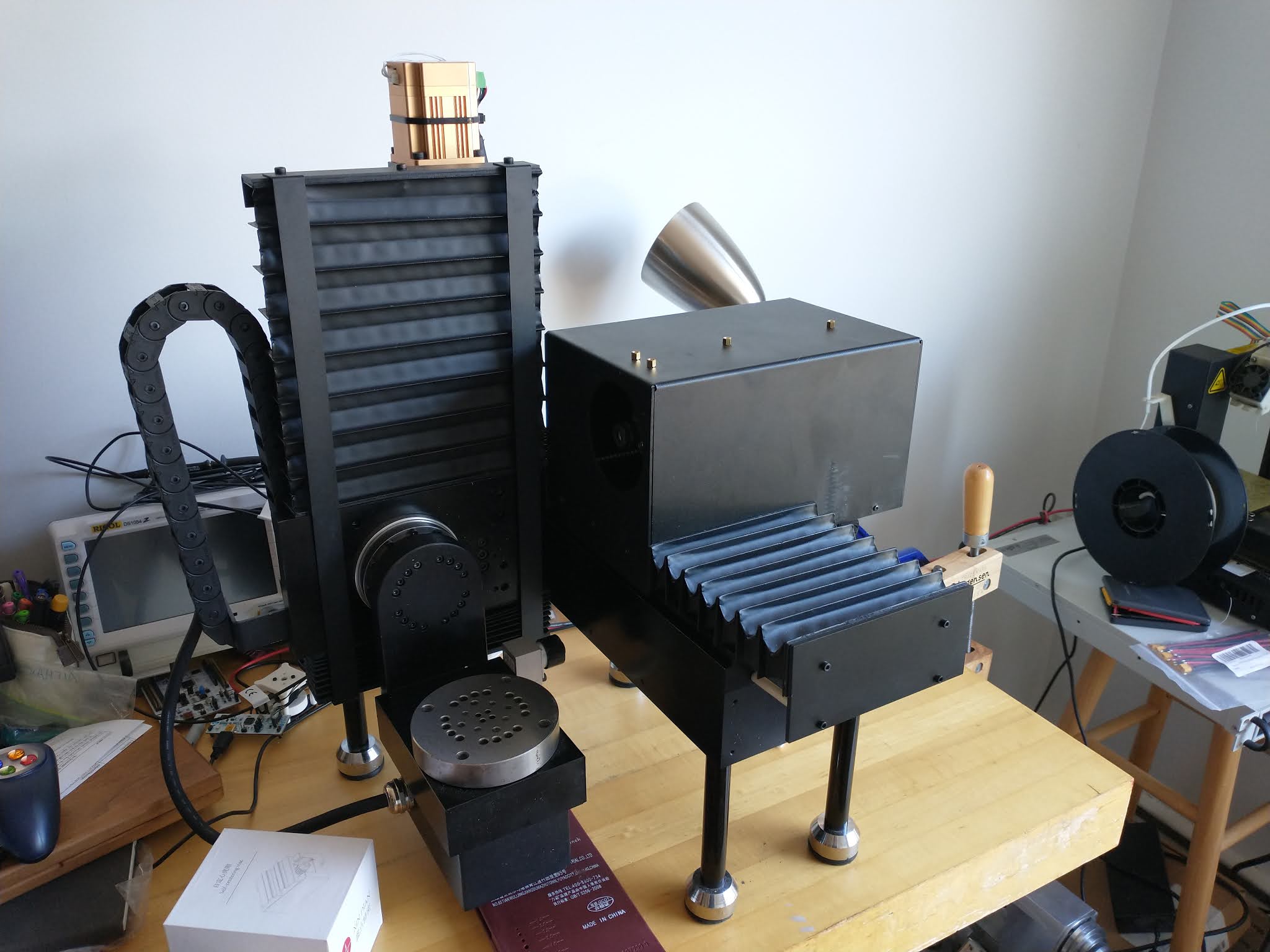
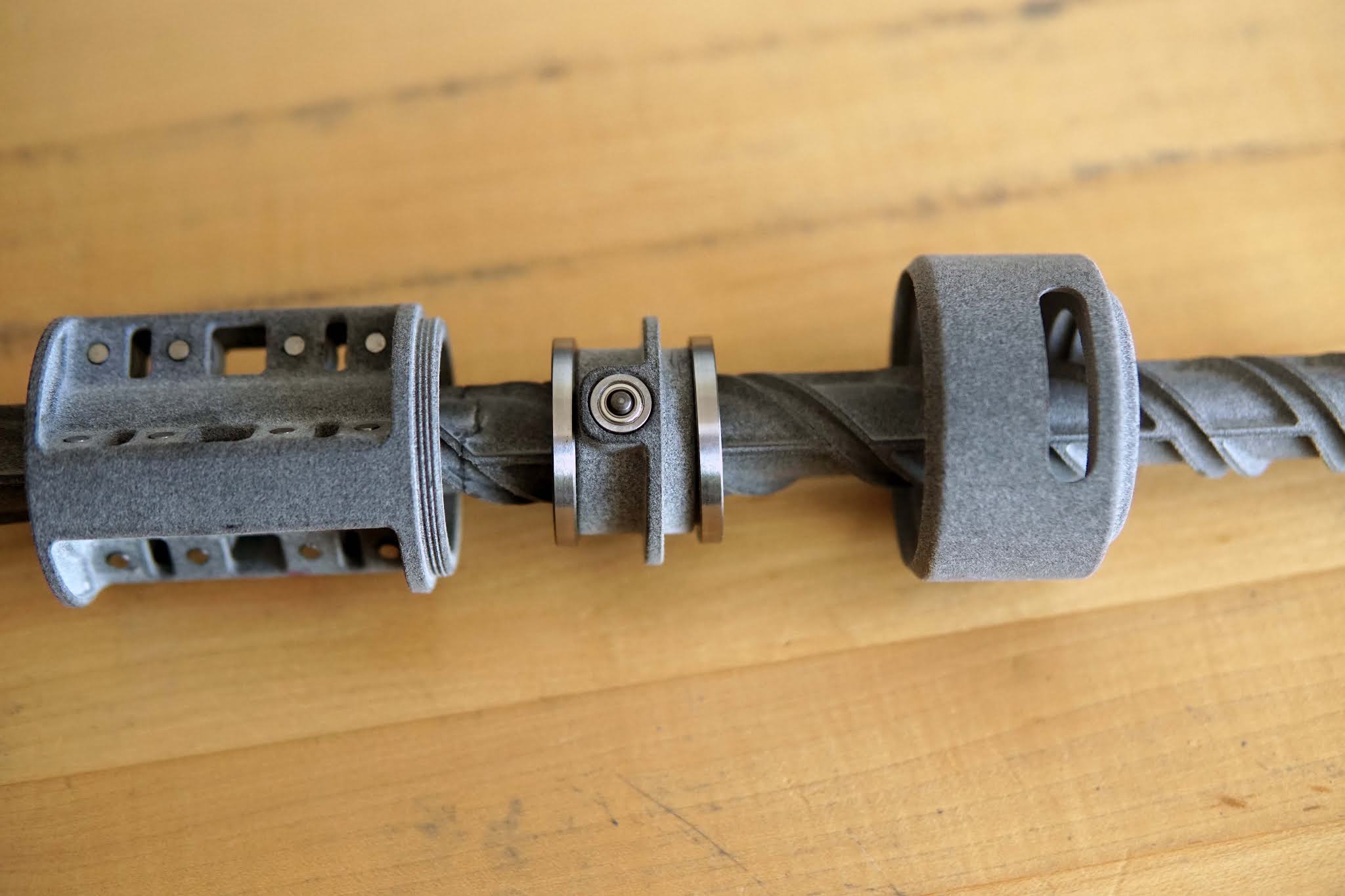
 Getting back to this mechanism.  In the post about the dynamics with varying transmission ratio, I came up with the design for the transmission profile by a combination of hand-calculations, intuition, and guesswork.  But we can do better.  

This problem fits nicely into a trajectory optimization.  For an intro to trajectory optimization, I'd highly recommend this MIT Underactuated Robotics chapter

I not-so-subtly hinted that the point of this mechanism was for jumping or launching things with an electric motor.  The simple English explanation of what I'm trying to do with a trajectory optimization here is answer this question:  What transmission ratio vs time maximizes jump height without breaking the mechanism? 

The optimization-lingo version of that would be something like:

Minimize \(-\dot{x}(t_{final})\), subject to:

  • Dynamics are not violated (i.e. \(x(t) = \int_{t_{0}}^{t_{final}} \dot{x}\,dt + x(t_{0})\))
  • Initial conditions (everything starts at rest, i.e. \(x(t_{0})=0\), \(\dot{x}(t_{0})=0\), etc)
  • \(\ddot{x} < a_{max}\), \(\omega < \omega_{max}\) (acceleration limit to limit forces, maximum motor speed)
  • And a few other things I'll get to later

I set up the problem using CasAdi, which is the same tool Jared and I used for the Mini Cheetah backflip optimization.  CasAdi makes it super easy to set up nonlinear optimizations like without having to understand what's going on in the back-end too deeply.  


Walking through my code (on GitHub here):

Pick some constants

The only "choice" here is the number of trajectory intervals.  Roughly speaking, too few will result in integration error, and too many will take longer to converge.  Everything else is just physical parameters:

1
2
3
4
5
6
7
8

N = 200              # number of trajectory intervals

m = .75              # mass            (kg)
j_rotor = 6e-6 	     # rotor inertia   (kg*m^2)
l_leg = .35 	     # leg length      (m)
tau = 1.6 	     # motor torque    (N-m)
w_max = 1200         # max motor speed (rad/s)
g = 9.8 	     # gravity         (m/s^2)


Decision variables

I took a "Direct Transcription" approach to the optimization - at each point along the trajectory, both the state (positions, velocities) and control inputs (transmission ratio and its derivative) are decision variables being optimized for.  As someone with not very much experience with this stuff, I found this easier to understand and implement than other methods (see here for several formulations).  I end up with a ton of redundant decision variables here (really there's only one independent one, which is the transmission ratio), but having position and velocity and acceleration and motor angular velocity and transmission ratio derivative as decision variables makes it very easy to put constraints on those terms.

Another note here, I have the final takeoff time as a decision variable.  This seems to usually not be a good idea (I won't pretend I can do an explanation justice), but this problem is simple enough that it works out.  Doing the Mini Cheetah backflips, for example, we did not do this, and fixed the takeoff times ahead of time (and did a little manual tuning to get the optimization to produce a nice result).  But that optimization had way more states and control inputs than this one.

Also, CasAdi is great.  foo = opti.variable(rows, cols), and you have a matrix of decision variables.

 1
 2
 3
 4
 5
 6
 7
 8
 9
10
11
12
13
14
15
16
17
18
19
opti = Opti() 		# Optimization problem

###  decision variables   ###
X = opti.variable(2,N+1) # position and velocity trajectory
pos   = X[0,:]
speed = X[1,:]

accel = opti.variable(1, N+1) # separating this out behaved better than including in X

U = opti.variable(2,N+1)   # transmission ratio and its derivative
k = U[0,:]
kd = U[1,:]

W = opti.variable(2, N+1)  # rotor angle and angular velocity
theta = W[0,:]
thetad = W[1,:]

T = opti.variable()      # final time


Pick a cost function

Often it's hard to describe what you "want" the optimization to do in an equation, have multiple competing objectives, and so on, but this problem is charmingly simple.  Maximizing jump height is the same as maximizing takeoff velocity, so we just minimize the negative of that.

1
2
#### objective  ###
opti.minimize(-(speed[-1])) # maximize speed at takeoff


Set up the dynamics constraints

This is the real meat of the optimization.  It implements the varying transmission ratio dynamics (with gravity this time) at every timestep along the trajectory.

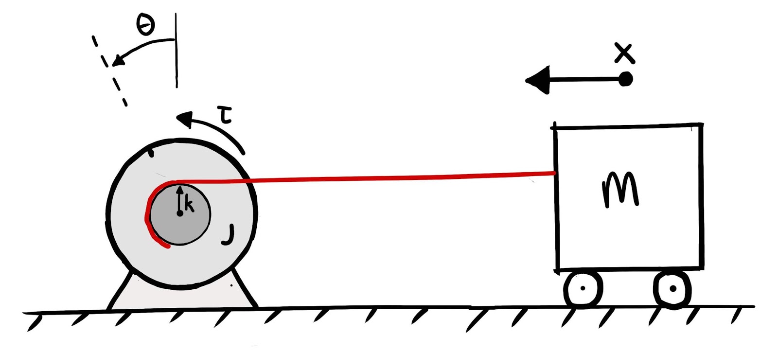
The equations of motion,

$$
\ddot{x} = \frac{k\tau + j\dot{k}\dot{\theta}-k^{2}mg}{j + k^{2}m}
$$

are implemented by the function \(f(x, u)\).  \(x\) is really the vector \([x, \dot{x}]\) at the timestep being evaluated, and u, the control input, is the transmission ratio and its derivative, \([k, \dot{k}]\).  It returns \([\dot{x}, \ddot{x}]\).

To ensure the dynamics are respected, there's trapezoidal integration constraints at each timestep, for all the states.  Basically, \(x(t+\Delta t) = x(t) + \Delta t\frac{(\dot{x}(t) + \dot{x}(t+\Delta t)}{2}\), and same deal for \(\dot{x}\), \(k\), \(\dot{k}\), and \(\omega\).

Finally there's the transmission ratio constraint, \(\dot{x} = k\dot{\theta}\)

 1
 2
 3
 4
 5
 6
 7
 8
 9
10
11
12
13
14
15
16
17
18
####  dynamic constraints   ###
f = lambda x,u: vertcat(x[1], (u[0]*tau + j_rotor*x[1]*u[1]/u[0] - m*g*(u[0]**2))/(j_rotor + m_body*(u[0]**2))) # dx/dt = f(x,u)


dt = T/N # length of a control intervals
for i in range(N): # loop over control intervals
   k1 = f(X[:,i],  U[:,i])
   k2 = f(X[:,i+1], U[:,i+1])
   x_next = X[:,i] + dt*(k1+k2)/2            # trapezoidal integration
   opti.subject_to(X[:,i+1]==x_next)         # dynamics integration constraint
   opti.subject_to(accel[i] == k1[1])			# acceleration

   k_next = k[i] + dt*(kd[i] + kd[i+1])/2	   # transmission ratio integration constraint
   opti.subject_to(k[i+1]==k_next)        

   theta_next = theta[i] + dt*(thetad[i] + thetad[i+1])/2 
   opti.subject_to(theta[i+1] == theta_next)	   # angle/angular velocity integration constraint
   opti.subject_to(thetad[i] == speed[i]/k[i])	# linear and angular velocity transmission ratio constraint


Bounds and boundary conditions:

The bounds are hard limits on the range of values the decision variables are allowed to take.  These are mostly based on physical constraints of building a variable transmission.  There are bounds on the derivative of the transmission ratio, so it doesn't instantaneously jump.  There are bounds on the transmission ratio itself, because it can't be infinite or too small.  The motor has a maximum angular velocity.  There's an acceleration limit to limit the forces on the transmission.

In addition to the bounds, there are some constraints on the initial and final state.  Everything has to start at rest at 0 position and velocity.  At the end, the extension of the "leg" should be the length of the leg.  The final motor speed should be small, so it doesn't crash into a hard-stop with too much energy.

 1
 2
 3
 4
 5
 6
 7
 8
 9
10
11
12
13
14
15
16
17
18
### bounds  ###
opti.subject_to(opti.bounded(0,kd,50))             # transmission ratio derivative bounds (no infinite slopes)
opti.subject_to(opti.bounded(0.0008,k,1))           # transmission ratio bounds (meters per radian)
opti.subject_to(opti.bounded(0, thetad, w_max))	   # maximum motor angular velocity
opti.subject_to(opti.bounded(.01, T, .5))          # reasonable takeoff time limits
opti.subject_to(opti.bounded(0, accel, 1000))      # acceleration limits


####  boundary conditions  ###
opti.subject_to(pos[0]==0)       # 0 initial position
opti.subject_to(speed[0]==0)     # 0 initial velocity
opti.subject_to(pos[-1]==l_leg)  # final position = leg length at takeoff
opti.subject_to(theta[0] == 0)	# initial rotor angle of zero
opti.subject_to(thetad[-1]<200)	# final rotor speed < 200 rad/s
opti.subject_to(thetad[-1] == speed[-1]/k[-1])	# linear and angular velocity transmission ratio constraint at the end
 
#### misc. constraints   ###
opti.subject_to(T>=0) # Time must be positive


Initial guess

The initial guess is the values for the decision variables that the optimization algorithm starts from.  For weird nonlinear trajectory optimizations, good initial guesses can make an enormous difference in the convergence speed and quality of the solutions.  A good example from my old lab is Gerardo's regularized predictive controller, which, as a flavor non-linear model predictive controller (MPC), runs a trajectory optimization at ~100 hz, so it can be used for (incredibly impressive) feedback control.  One of the many things that lets that optimization run at 100 hz is a good initial guess (a.k.a. "warm starting").

But this problem's simple, so I did a few runs starting from guesses of zero for everything, and picked what looked like the "average" values of the solutions I got as the new initial guesses.

1
2
3
4
####  initial values   ###
opti.set_initial(k, .02)
opti.set_initial(kd, 0)
opti.set_initial(T, .2)


Solve:

Set up and solve the problem with the solver of your choice.  I used IPOPT because that's what we used for Cheetah stuff.  I played around with a few others and didn't get any better results.

1
2
3
### solve  ###
opti.solver("ipopt") # set numerical backend
sol = opti.solve()   # actual solve


And that's it.

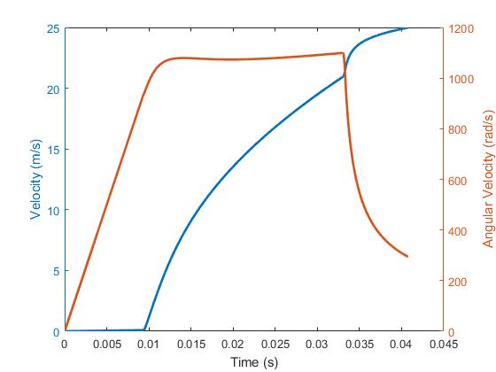
Here an example solution:

Here you can see how the kinetic energy of the mass, of the rotor inertia, and the potential energy of the mass trade off over the trajectory:


Compared to the hand-designed version of the transmission profile, the optimized one can exactly max out my acceleration constraint, exactly max out the motor speed constraint, and rapidly decelerate the motor to my threshold at the end (ignore the acceleration at the last timestep, it's not meaningful):


Below is an example of an optimized transmission ratio vs rotor angle on the left, vs my hand-designed one on the right.  The mass/torque/inertia/stroke used for these are different, so the absolute numbers shouldn't be compared, but qualitatively, I was definitely on the right track with my hand-design.   Which is always satisfying to see:


The numbers I'm seeing out of the optimization are nearly 10 meters (if I can hit the weight target in there), so things are going to get exciting.

November 15, 2020

Music Server

Until Google axe-murdered it recently, I used Google Play Music to store my music collection and stream it to my various devices.  I didn't pay for a subscription, just uploaded all my music files to Play, and treated it as free storage, organization, and streaming.  Rather than switch over to YouTube Music (I tried, it was utter garbage) or some other streaming service, I took this opportunity to set up a personal music server.

My music buying and listening habits are a little unusual:

  • I want a digital copy of my music backed up on storage I own
  • I purchase and download full albums (not single songs)
  • I almost always listen to full albums (no shuffling, auto-generated playlists, etc).   
So I'm not really into the idea of subscription-based streaming services.  Compounding my dislike of streaming subscriptions, I want my money to actually go to the musicians who make the music I listen to, and streaming just doesn't do that very well.  

For the last few years, I've been tracking my album purchases as well as how many total song plays I have.  Here's what my cumulative music spending looks like since April 2018:


Since then, I've spent an average of $13.64 per month on buying albums, which is slightly more than a Spotify membership.  Looking at the sources I've purchased the albums from (directly from artist websites, Bandcamp, Amazon, etc), on average 76% of my spending goes towards the rights holders - $332.98 since I started keeping track.  If I had used Spotify, on the other hand, the total payout to rights holders would have been on the order of $65.60, given how many plays I've logged in that time (~20,500 plays, assuming .32 cents/stream).

So I spend 36% more a month on music than a Spotify subscription would cost, but 5 times as much of my money makes it to the music's rights holders.  Some other service than Spotify might be better (according to the source I linked to, Amazon pays out ~3.7x what Spotify does per-stream), but either way, given my listening habits, buying albums seems like the way to go from an artist-profit perspective.  

The Setup:

I'm now hosting my music on a Raspberry Pi running Airsonic.  For storage I'm using a pair of USB flash drives in mirrored RAID.  

I'm not going to write up a full how-to, but here's a list of resources I used and notes from setting it up.  It was surprisingly straight-forward, even though I'm no Linux wizard and have never self-hosted a website before.
  • Setting up the flash drive RAID array
  • Installing Airsonic on a Raspberry Pi.  The only thing I did differently from this guide was use open-jdk rather than oracle-jdk.  Skip past the "Set up a reverse proxy" portion for now.
  • I got a domain name on Google Domains, installed ddclient on the Pi, and followed these instructions to set up dynamic DNS so the domain points towards my router's dynamic IP address.
  • I struggled for a while with getting a TLS certificate using certbot.  It turns out my ISP blocks port 80, so I followed these instructions to get a certificate using port 443.
  • Airsonic Apache reverse proxy setup.  Once I could reach my domain name from outside of my local network, I followed these instructions.  This just worked, so my Airsonic login showed up at <my_domain_name>.com/airsonic.
  • Airsonic works best with an Artist/Album/SongName folder structure, so I used MP3TAG to re-organize my files, following the instruction here.  It was fast and worked great.
And that's pretty much it.  I've had no problems with the browser-based playback, and the Android app Subsonic seems like it works, but I haven't tested it much.  

October 28, 2020

Another batch of furuta pendulums

 I did another batch of Furuta pendulums and took a timelapse of the assembly:


These were done in a bit of a hurry, and nothing was changed from last time.  At some point I'll probably do a refresh of the design, though.  After building 16 of these, I have a bunch of ideas about things I'd like to do differently, and I've gotten a few feature requests from the recipient as well.  

And now, back to the other things in the pipeline.

October 6, 2020

Benchtop 5-Axis Mill

This was inevitable, but the pandemic has accelerated my home-shop setup.  What with leaving the lab almost a year ago (I miss you Lab Haas) and no MITERS for the foreseeable future, I haven't had access to any machine tools other than the tiny lathe for a while.  Time to fix that.

I've been following Pocket NC since 2012, after seeing them at the NY Maker Faire - they make a tiny but surprisingly capable 5-axis CNC mill.  It has basically the same layout as the big GROB machines, with a horizontal milling spindle moving in Z and X, and a cantilevered trunnion on the Y axis.   I was tempted to get one of their machines, but I think they're just too small and underpowered (and pretty expensive) for the sort of parts I make.  In my search for a small-enough-to-carry-upstairs-into-my-living-room-but-not-too-small CNC mill, I ran across a scaled-up Pocket NC clone made by a Chinese company, Xinshan Tech.  I couldn't find any examples of real people outside of China owning the machine, but after some emails back and forth with the company, including a bunch of videos, I was convinced that the machine was real and not a scam.  This machine was appealing, since it's a fair bit bigger than the Pocket NC, with ~50% more travel in each axis, all steel, servo (rather than stepper) driven, and much heavier (~70 kg).  I've gotten along just fine with 3-axis machines up until now, but I couldn't actually find any 3-axis mills that fit what I was looking for any better, and 5-axis opens up some interesting opportunities.

I decided to go for it, and a month later DHL showed up with a heavy crate:


Out of the crate and on the bench.  The machine is deceptively heavy given how small it looks, and is very awkward to hold onto.  Rigol scope in the background for scale.  


Back side of the spindle visible:  It's a generic 800W ER-11 water cooled spindles.  Maybe something to upgrade in the future:


The three linear axes are driven by brushless servos with integrated controllers:


A peek under the bellows way covers at the (allegedly Hiwin) X-axis ballscrew and one of the linear guides:


The linear axis ballscrews are coupled to the servos with disc couplings, which is nice to see


The backside of the machine, where you can see the X,Y, and A axis servos.  The rotary axes are driven with harmonic drive reductions and supported by crossed roller bearings, which I'm surprised was possible given the cost.


When I unpacked the electronics box, a few screws had worked loose in shipping and were rattling around.  The inside of the electronics box was not confidence-inspiring.  There's a generic 36V DC supply to run the servos, a 1.5 kW VFD, and some pretty sketchy wiring.   The machine seems good mechanically, so I'm letting this slide for now....


I've been using the shipping crate it came in as an enclosure.  If I fold the door up it keeps the chips in and the noise down a little, at the cost of seeing what's going on.  Eventually I'll build a proper enclosure.  I set the crate on top of a Harbor Freight rolling tool cart, which stores the power supply box, water cooling, and related tools:


Screenshot of the the control software below.  The software isn't anything fancy, but does the job.  There are amusingly mis-translated buttons like "Knife", which actually runs the tool probing macro, "overrate", which is the feed override, and "Cold Fog", which presumably would turn on mist coolant if the machine had it.


Not particularly exciting, but here was my first working attempt at a multi-axis toolpath (video at 16x):


Here's one of the first "real" parts I've made - the front side of a motor housing.  Most of the material removal was done with a Datron 3mm single-flute end mill.  Thanks to the rotary table I could do this part in one setup, rather than machining one side, machining a fixture, and machining the other side like I would on a 3-axis machine.  Video at 8x speed.


Here's pretending the mill is a lathe and machining a shaft for said motor, including a lock ring thread cut with a 60 degree chamfer mill.  HSMWorks, which I've been using for CAM since the beginning, is pretty terrible for this style of toolpath, so the surface finish is a little weird.  It buffed out easily though.  In this picture the part is done and being parted off:


And here's that half-a-motor-housing and shaft with a rotor for a frameless motor installed (held on by a threaded lockring also made on the mill), and bearings and commutation encoder magnet pressed in.  


I haven't pushed the machine too hard yet, in the interest of keeping noise down.  It's in my 2nd floor living room, and not very well enclosed, so I've been making the toolpaths conservative to avoid complaints from my neighbors.

Amusing setup from today - a part in the tiny lathe 3-jaw chuck, held in an ER-40 collet chuck, bolted to the table.  Milling a circular dovetail in the part (which is a fixture for yet another part), to match the dovetails milled into the lathe chuck soft jaws:  No dovetail cutter required.


Summary of thoughts/impressions so far:
  • The core mechanical pieces of the machine seem pretty good.  Brushless servos, linear guides, ballscrews, and harmonic drives, on a steel structure is impressive at this price point.
  • The less-critical hardware is a little janky - the bellows way covers, the sheet metal spindle cover, the electronics box, the water cooling loop.  But those are all relatively straightforward to re-do or repair if needed.
  • With good tools (I've been having great luck with Datron single flute cutters for roughing), it performs pretty well cutting aluminum.  I've been roughing with a 3mm endmill at 20k RPM, 2.5mm stepover, .5mm stepdown, and 2000mm/min feed with no problem.  It could definitely be pushed harder but it gets loud.  I haven't tried harder materials yet.
  • I haven't done a ton of experimenting yet, but "conventional" style toolpaths with large stepover and small stepdown seem to perform better than "adaptive" or "trochoidal" style toolpaths with a large stepdown and small stepover.  Needs more testing though.
  • I wish I had a way to pre-set tool lengths with the ER-11 spindle.  The machine has a built-in tool probe, but swapping collets and probing takes a while.  I'm thinking about making a bunch of shrink-fit holders that all have the same shank diameter and bottom out in the spindle, so the collet and collet nut never have to come all the way off. 
  • There are a few vendors of the machine (It's even on Amazon, but also RobotDigg and a few other sites), but it's cheaper to get directly from Xinshan.  
  • Support has been really excellent so far.  I've had tons of questions about how things work, and I always get a response the next day.  When I've had g-code that behaves confusingly, they'll run the code on their machine and send me a video.
  • CAM-wise, I've been using HSMWorks.  I think the kids these days are using Fusion 360 (Autodesk bought HSMWorks and I think has ported it into Fusion), but I've never tried it.  Solidworks integration is super nice since your CAM updates when your model updates, and I don't really want to switch to Fusion for CAD.  HSMWorks/Fusion 4/5-axis toolpaths are kind of a joke, but 3+2 (position the rotary axes then do a 3-axis toolpath) work great.  The "real" answer for good 5-axis toolpaths is probably a more legit stand-alone CAM software, but I'm going to stick to HSMWorks for everything I can.  
  • Cool feature, the machine can do TCP, Tool Point Center control - this means that the CAM origin does not need to be at the machine origin (the intersection of the two rotary axes).  You can put the CAM origin wherever, set the work coordinate system offsets by touching off to the part, and the machine will figure out the kinematics.  This makes CAM much simpler, since you don't have to know where the part/stock are on the machine when you're doing the CAM.  That's what you'd expect for 3-axis stuff, but with the two rotary axes, it's not just an offset in X, Y and Z anymore.  I haven't been to adventurous with this, but offsetting the Z at least seem to work just fine. 

August 30, 2020

Varying pitch screw mechanism

I put together a mostly-3D-printed prototype of the variable-pitch screw idea.  Although it looked like it would work in CAD, I wanted to get a feel for the mechanism in real-life before designing anything around it:


The mechanism combines a cylindrical cam with linear motion constraint all on the same cylinder.

The main pieces besides the screw are shown below.  On the left is the linear constraint mechanism, which has 6 rollers in it.  In the center is the "nut" which has two cam followers pointing radially inwards.  The cam followers engage with the spiral slot around the screw.  On the right and left of the nut are bearings which take the thrust load from the screw, and constrain the nut.  On the right is a cap, which just supports one of the nut bearings.  It threads on to the linear mechanism, sandwiching the nut.

wow, blogger has alt text now

A better view of how the linear motion constraint works.  3 V-grooves go down the length of the screw.  6 plastic rollers on bearings ride in the V-grooves, preventing the screw from rotating or tilting:


The V-grooves are shallow enough that they don't interfere with the spiral cam slot:


Here's a cross section of the linear motion constraint.  There are 4 rollers per V-groove, and the rollers are carefully spaced such that 2 spaced far apart from each other are always engaged with the V-groove, even while one or two other roller is jumping over spiral slot.


Below you can see the makeshift cam followers inside the nut.  Each cam follower is a dowel pin pressed into a pair of flanged bearings.  For a "real" version of this I'll need to come up with something less janky, but this was good enough to check that the mechanism actually worked.


The linear constraint rollers were machined on the Tiny Lathe.  I used a diamond needle file to hand-grind a form tool out of an HSS blank.  The whole roller profile was turned in one pass by plunging the form tool in a set depth.  The bore for the bearings was also done in one pass, by offsetting the tailstock to one side, and boring it out with a ballnose end mill in the drill chuck.  Delrin is soft enough that you can get away with stuff like this.

Here's a picture of the form tool next to one of the rollers in the assembly:


The screw CAD was generated by creating a CSV of coordinates in MATLAB, importing it as a spline into SolidWorks, and sweep-cutting a small-diameter cylinder through a hollow tube, following the spline.  Kind of a finicky process, but it works.  If I decided to change the profile later on, I can replace the spline points with new set, and most of the dependent features are able to regenerate.


July 22, 2020

A decade of project blogging

I just noticed that as of this month, I've had build-its.blogspot.com for 10 years.  It's hard to believe how long it's been and how short it's felt.  Hopefully Blogger is still around in another 10.

For nostalgia's sake,  here's the oldest project-thing I've documented- strapping model rocket engines to a pinewood derby car:  This video predates the blog - I think it was filmed in 2007.


2nd place goes to this shot of me planing a railing on The Boat from 2009. 

June 6, 2020

Simple Dynamics With Varying Transmission Ratios

An idea I've had in the back of my head for a while now is using varying transmission ratios to transfer kinetic energy between bodies.  That sounds really abstract, but I'll explain.

Here's a simple example that frames the problem.


There's a mass, \(m\), which can translate in \(x\).  Driving the mass is an actuator with inertia \(j\) and angle \(\theta\).  There's a transmission between the rotation of the actuator and the translation of the mass.  The transmission ratio, \(k\), is the ratio between angular velocity of the actuator and linear velocity of the mass, i.e. a radius.  This radius varies as the angle of the actuator changes.

Below is a sketch of how a varying transmission ratio might look, with a pulley that changes radius as it winds up:


The specific idea I wanted to test out was this:
Start out with a low transmission ratio, so spinning the inertia doesn't move the mass very much.  "Spool up" the inertia to high speed.  Vary the transmission ratio so the mass accelerates at constant power, but the inertia speed is constant.  Then, rapidly increase the transmission ratio.  This should cause the inertia to decelerate, transferring its kinetic energy to the mass.

At least, that's intuitively what I would expect to happen.  It's similar to the idea of revving up an engine and dumping the clutch to accelerate hard (or do a burnout), but in the clutch case, half of the kinetic energy is necessarily dissipated by slip in the clutch.  In the variable transmission ratio case, there's no slip, so there shouldn't be any energy loss.

Jumping into the dynamics:
Instantaneously, the relationship between angular velocity and linear velocity is:
$$\dot{x} = k\dot{\theta}$$
Differentiating, the relationship between accelerations is:
$$\ddot{x} = k\ddot{\theta} + \dot{k}\dot{\theta}$$
Normally, with a fixed transmission ratio, \(\ddot{x} = k\ddot{\theta}\).  But if the transmission ratio isn't constant, another term shows up.  If the transmission ratio is increasing and there's positive angular velocity, there's an additional positive acceleration.  That's in-line with the intuition so far.

If a constant torque \(\tau\) is applied to the actuator, the acceleration of the mass works out to the following:

$$
\ddot{x} = \frac{k\tau + j\dot{k}\dot{\theta}}{j + k^{2}m}
$$

Rather than the transmission ratio being time-varying, say it's position-varying.  Imagine a cable spooling up on a variable-radius pulley, or a cam follower rolling along a cam.  Recognizing that if \(k = k(\theta)\), then \(\dot{k} = \dot{\theta}\frac{dk}{d\theta}\), the acceleration is:

$$
\ddot{x} = \frac{k\tau + j\dot{\theta}^{2}\frac{dk}{d\theta}}{j + k^{2}m}
$$

This position-derivative variant is nice because it can be pre-computed from k vs position, rather than requiring time-differentiation to get.


Going back to the idea I wanted to test: Spool up the motor to high speed.  Operate at constant speed and power.  Then spool down the motor to transfer the actuator's kinetic energy to the mass.

I roughly hand-designed a varying transmission ratio to do this.  At the beginning, there's a constant, small transmission ratio.  Then it switches to a logarithmic curve -  A log curve results in constant power output at constant actuator angular velocity, although I'm not going to justify that here.  At the end, it rapidly increases to slow down the actuator.

Here's a plot of the example transmission ratio vs motor angle.  Polar version of the plot on the right:


And a rotating GIF for good measure:


Simulating the dynamics, here's what I get when applying a constant torque to the actuator.  Actuator angular velocity and speed of the mass are plotted below.  First, when the transmission ratio is tiny, the angular velocity ramps up but the mass barely moves.  Then when the transmission reaches the logarithmic section, the angular velocity becomes roughly constant.  The mass accelerates at constant power.  Finally, the steep end section of the transmission is reached, the actuator angular velocity quickly decreases, and there is a corresponding jump in mass linear velocity.


Plotting the kinetic energies of the actuator and mass, vs the input energy, \(\int{\tau\omega}\), you can clearly see energy trading off between the actuator and mass.  No energy is lost - the kinetic energies at the end are equal to the input energy:


Changing gears (ha), here's what a solid model of a pulley with this profile looks like:


And rather than a variable-radius pulley, the same transmission profile can also be implemented as a variable-pitch screw (or maybe technically a barrel cam).  A pair of cam followers ride in the grooves and act as the nut:


Stay tuned, prototypes coming up soon.