August 29, 2016

Introducing the GigaTroller

Enjoy this unprecedented two posts in one day.  It probably won't happen again.

The GigaTroller is the motor controller designed for running the absorber on the motor dyno, named for the absurd mosfets it uses, the IXYS MMIX1F520N075T2 TrenchT2 GigaMOS HiperFET. What a mouthful.

This is an rediculous mosfet.  Rdson is quite good but not spectacular (given its size), typically 1.2 mΩ on a 75V FET, and it has quite a lot of gate charge, 550 nC at 10V on the gate.   However, mechanically it's pretty awesome.  It's some fancy IXYS surface mount package, 1" square, with an isolated metal pad on the top.  Thanks to the presumably gigantic die and excellent package, it's rated for 500 A at 25 C, 1700 A pulsed, and 830 (!) watts of package dissipation at 25 C.  It's also a whopping $17 per FET on Digikey, but fortunately Bayley found some rails of them for $5 each on Ebay.  At $17 they would be silly to buy but it's actually a pretty reasonable amount of transistor for $5.


Nominally I'm designing this controller for 200A, 50V operation, because that's all the dyno absorber can do.  This should be very safely within the ratings of these transistors.

A tricky thing about designing a high current controller like this is designing a PCB that can actually handle that current.  To make the controller as compact as possible, I designed it to use custom surface-mount busbar, which I waterjet cut out of copper plate and reflowed to the PCB.  Another interesting feature of this transistor package is that it physically has a cutaway underneath the package between the legs.  I'm using that space to route the busbar beneath the transistors, instead of next to them.


Here's a board from 3PCB and a pile of busbar.  Although I didn't ask for gold plating on the PCB, I got it for no extra cost.  Presumably my boards were tacked onto a big batch that was getting plated or something?


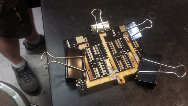
It took two tries to solder the bus bar.  First time around, I tried clamping everything at once and baking it in an oven, but that ended up warping the board and turning out poorly.  At Peter's suggestion, I soldered the busbars one-at-a-time, fixturing them with steel binder clips and heat-gunning them with solder paste underneath.  This worked out beautifully:


After sanding off excess solder and oxidation:


Here's the power board populated with FETs, Allegro current sensors, gate pulldowns and gate zeners, and one 22 uF film cap per leg.  After reading this paper, I decided to try out using just a small-ish set of film caps instead of the the huge pile of electrolytics I'm used to seeing.


Note the bus bar routed underneath the transistors:


Logic and gate drive stack on top of the controller, next to the capacitors.  An STM32F446 does all the motor-control stuff.  I know the F3 series are probably a better choice for motor control things, but I had a few F446's left lying around, and this way I could just port all my FOC code over from my small controllers with minimal editing.

The power supply section of this features 5 isolated 15V DC supplies - one for the low-side gate drivers, one for each of the three high-side gate drivers, and one one for the logic.  The gates are driven by 2.5A gate drive optoisolators.


Bayley actually designed the power supply and gate drive section of this for different motor control project of similar power level, so I borrowed his design.  A 555 generates a square wave, which is fed into the inputs of a dual inverting/non-inverting gate drive IC.  The gate driver swings around the primary of a 6-winding transformer, the 5 other windings of which are rectified to generate the 5 isolated 15V supplies.


The gate drive IC driving the transformer gets extremely warm, but its power dissipation is still within spec, and it's now operated 10's of hours at least with no problems.  When the controller gets mounted to a heatsink I'll make sure it gets some airflow too.

I used ethernet connectors for programming/serial and position sensor, because they're nice cheap, locking, small-footprint connectors.  And they're matte black.


To get the controller working, I spent a few days figuring out how to generate complimentary PWM signals with software-defined deadtime.  That was the only significant code change, though, other than re-doing the current loops as usual.

So far I've pushed the controller to 45V, 100 phase-amps entirely without drama.  The transistors get a little warm.  Here's what bus voltage looks like at ~80 phase amps.  Note this is running of a bench supply with several feet of wire between the supply and controller.  At 41 volts on the supply, the sharp spikes hit ~7.5 volts above nominal, and the bulk ripple is a couple volts.


Here are the Eagle files, if for some reason you want to build one of these:
Power Board
Logic Board

Small Motor Dynamometer: The Beginnings

Where "Small" means around 6-7 kW.

I've been ruminating on building a small motor dyno for a while, since spending most of last summer working with really big dynamometers.  While strategies like listen to the strange noises your motor is making to find glitches in your control loop and use your hand to load the motor and see how it behaves are surprisingly informative (and certainly help develop some intuition), they don't really give you any quantitative information about motor performance (although I'm learning to calibrate my wrist as a torque sensor).

For those unfamiliar with what a dynamometer is and does, it's basically a system that lets you characterize a motor/engine/other torque-producing device.  The output of the motor is coupled to speed and torque sensors.  Speed times torque gives the actual mechanical power coming out of the motor.  At the same time, voltage and current going into the motor can be measured, giving the power going into the motor.  On the other side, another motor, called the "absorber", acts as a generator to absorb all the power put out the the motor being tested.

For several months my ebay home page was filled with a variety of different searches for torque sensors, and eventually I found an excellent deal on a used S. Himmelstein DC-operated torque transducer, good for 11.15 Nm of torque and 6000 RPM.  It's almost perfectly matched to one of the 80-100 sized brushless outrunners, which is just about the biggest motor used in the various contraptions my friends and I build.  The DC-operated versions of the Himmelstein torque sensors are especially convenient, since they just output analog DC voltage proportional to torque, which can be shoved into a DAQ for logging.  Lots of the ebay-torque transducers require extra (expensive) circuitry to run the rotary transformers which interface with the strain gauges.  I'm really impressed with this torque sensor - plugging it into a 16-big USB DAQ, I can easily distinguish 0.001 Nm changes in torque on the sensor, which is 1/10,000th of full scale.

For the absorber, I started out with the original 80-100 from the electric trike, which Charles gave to me 4 years ago.  When it originally stopped working due to some shorted windings, I pulled off the original windings and then it sat around until now.  I did the rewind with 4 parallel strands of 16 AWG, 200 C rated magnet wire, five turns-per-tooth, wye terminated.  There's still a little space between the stator slots, which I wanted for improved cooling (there will be a blower to force air through the stator).


After the rewind, the motor sits at:  13 mΩ  line-to-line, and a torque constant of 0.062 N-m/A.

I made a base plate out of a slab of 3/4" thick aluminum I found in the trash.  The motor shaft was carefully aligned to the shaft of the torque transducer, and they were coupled with some custom-machined lovejoy couplings (I bought the flexible inserts, and machined the aluminum bits):


Here's the coupling pair.  The absorber-side of the coupling bolts directly to the bolt pattern where one would normally attach a propeller mount, and locates on the 12mm shaft which passes through the length of the rotor.  On the torque transducer side, the coupling is keyed and axially retained by a set screw into the key.


On the input-side of the torque transducer, there's an ER-32 spindle, to make it easy to couple in arbitrary motors.  I got an cheap ER-32 straight shank collet holder on ebay, reamed out the inner bore, added a split, and made a big split collar to clamp the whole assembly together.  I measured runout on the inside of the spindle taper at one thousandth of an inch, which is definitely good enough.  The test-motor will be mounted on a compliant mount, to avoid over constraint.


The feet of the absorber and the torque sensor each locate to the base with three dowel pins, so I can repeatably assemble and disassemble the whole thing.


So that's a brief introduction to the motor dyno.  Next post (which will be soon) will go into the motor controller I'm using on the absorber, as well as some initial testing of the whole thing.

August 26, 2016

Desktop Inverted Pendulum Part 2: Control

With the mechanical bits out of the way, it's time to go through the process of controlling the inverted pendulum.  Brace yourself for babble about transfer functions and other controls stuff.  Video at the end.

First on the agenda is getting the brushless motor to actually produce torque.  While I'd already done 99% of the work required, I still had to redo the current d/q axis current loops.

After some decoupling the motors d and q axes look like independent RL circuits, and are thus easily tamed with PI controllers.  Since the control loops are running on a microcontroller, it makes sense to design them directly in discrete time, rather than in continuous time (although designing in continuous time, assuming you sample fast enough for it to not make a difference, and converting to discrete time can be valid too).  To do so, first find the zero-order hold equivalent of the RL circuit - basically, how the dynamics of the circuit appear to the microcontroller sampling at a fixed rate.

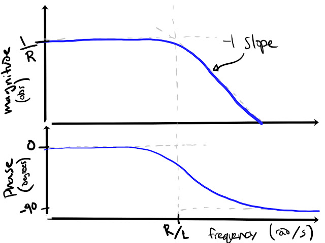
Remembering good ol' 2.004, the transfer function of a series RL circuit from voltage to current is $$\frac{I(s)}{V(s)} = \frac{1}{(Ls + R)}$$ which has a frequency response like this:


Now let's convert that to discrete time.  Some amount of algebra (or numerically in one line of Matlab using c2d) later, you get:
$$\frac{I(z)}{V(z)}=\frac{\frac{1}{R}\Big(1-e^{\frac{-R\dot{}Ts}{L}}\Big)}{z -e^{\frac{-R\dot{}Ts}{L}}}$$
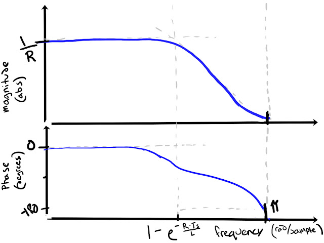
 Where R and L are the same resistance and inductance as before, and Ts is the sample period.  The frequency response looks a lot like the continuous time version, except that the phase (and magnitude, but to a lesser extent) gets kind of wacky towards π radians/sample.


Okay, now to design a discrete current loop.  I like to write a PI controller in the form
$$\frac{U(z)}{E(z)}=k\Big(1 + \frac{ki}{z-1}\Big)$$
which has a pole at z=1, a zero at z=1-ki, and a high-frequency gain of k.  This way, changing k only changes the loop gain, and changing ki only changes the zero location, unlike the typical parallel PI expression.

Set if we set the zero of the controller on top of the pole of the RL system, then the controller * RL just looks like an integrator.  This can be done by setting $$ ki = 1-e^{\frac{-R\dot{}Ts}{L}}$$

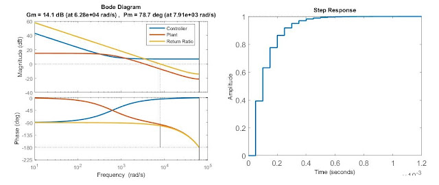
Now just to choose a loop gain that achieves whatever crossover frequency (ωc) you want.  Let's say something like π/8 radians/sample, to be conservative, because, to quote a professor, "There are always higher-order poles".  This should be reasonably conservative and give us ~78 degrees of phase margin, as you can tell from the pole-zero map of the return ratio (in this case the circuit times the controller, which is just an integrator):


From the same geometry, you can see that crossing over at ωc = π/2 gives you 45 degrees of phase margin, etc.

We can calculate approximately the loop gain required by doing some more geometry on the bode plot of the return ratio.   We want the loop to cross over (magnitude = 1, or 0 dB if you prefer dB for some reason) at  π/8 radians/sample.  We also know that, at the frequency of the controller zero and circuit pole, the plot has a magnitude of k/R.  Since the slope of the magnitude plot is -1 (on a log/log scale), we can easily calculate the k required to join those two points with a line of the correct slope:


So k should be ...
$$k=r\Bigg(\frac{\omega_{c}}{1-e^{\frac{-R\dot{}Ts}{L}}}\Bigg)$$
This won't be quite exact, because the slope of the magnitude plot isn't perfectly -1 between those two points, but it gets you pretty darn close.

Here's some MATLAB plots verifying the frequency and step response of the current controller designed this way.


Hey, I just worked that all out symbolically.... that means that if my motor controllers could measure resistance and inductance on their own, they could auto-tune their current loops....(also note this isn't specific to current control of RL circuits.  It can just as easily apply to any 1st-order kind of system, like velocity control of a motor (inertia -> inductance, damping -> resistance), etc)


With torque (well, current, but close enough) control out of the way, next step is stabilizing the pendulum upright.  While there's always the "I heard PID controllers were good so lets throw PID at it and plug in arbitrary constants until it works" strategy, which people on the internet seem to like, that's not very interesting.  There are lots of reasonable approaches, but the one I've mostly been playing with is full state feedback with LQR-chosen gains.  While I've taken a class on state space modeling and controls, I had never actually implemented such a controller in hardware, on a microcontroller.

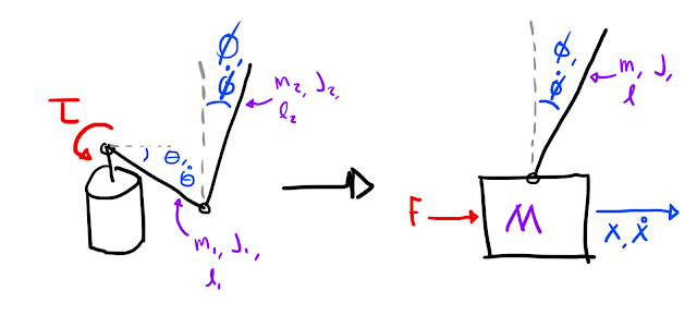
Like most good controls problems, the first step is coming up with a model of the system to design the controller around.  For the near-upright position, the furuta pendulum system can be greatly simplified from the extremely unpleasant full equations of motion.  Rather than doing the proper thing and linearizing those about the pendulum-up position, I was lazy and converted my rotary inverted pendulum into a cart-pole, and linearized those equations about vertical.  Except that has been done for me dozens of times.

The quantities that need to be converted to go from the rotary inverted pendulum to cart-pole:


The only trick is that care needs to be taken doing this conversion- both going from physical device to the model, and from controller gains back to the physical device when implementing the controller.  In the model, the units are meters, kilograms, and Newtons, whereas on the device they are radians, kilogram-meters^2, and Newton-meters respectively.  This model is only valid for small rotations on both axes, but it seems to be good enough to stabilize the system well.

The upright-controller, for reference states of zero, looks like this: $$ \tau = 0\dot{}\theta - 0.1\dot{}\dot{\theta} + 2.52\dot{}\phi + 0.15\dot{}\dot{\phi} $$ where  tau is torque, theta is the angle of the base, and phi is the angle of the pendulum (from upright)

Something to note:  I put no weight on the location of the pendulum (i.e. the x-position of the cart in the cart-pole system), so the gain in front of theta is zero.  This was mostly an aesthetic choice - I thought it would look nice if the pendulum slowly coasted to a stop after being disturbed.

Positions are taken straight from the sensors.  Base velocity (theta dot) is measured with this trick, and pendulum velocity is the (heavily filtered) derivative of angle, since I can't time edges on the Allegro A1335 position sensor used for pendulum angle.

Here's the disturbance response (i.e. me flicking the pendulum) of pendulum angle with two different controllers, as compared to the model used to come up with the controller gains.


To actually get the pendulum to the upright position, I (roughly) used an energy-shaping controller.  Check out the 6.832 notes here for a more detailed description of how that works.  The basic idea is to apply a torque to the pendulum only when it adds energy to the pendulum, and only do so while the pendulum has less than its upright energy)  In other words, the sign of the torque applied to the pendulum should be the same as the sign of the angular velocity of the pendulum, so that torque times angular velocity (i.e. power) is positive.   By doing the opposite, you can remove energy from the system, if you want to swing down from upright, for example.  At the end of the day, my energy shaping controller looks like:
$$\tau{} = K\dot{}cos^4(\theta{})\dot{}\dot{\theta{}}\dot{}(9.81(1-cos(\theta{}) )-.0075\dot{\theta{}}^2)$$
Tau is torque, theta is the pendulum angle.  K is a constant found through experimentation.  The 9.81-.... term at the end is proportional to the additional energy needed to bring the pendulum upright.  The 4th power cosine term has the effect of skewing the controller output towards the bottom of the swing, when the pendulum velocity is the greatest.  This term was actually sort of an accident.  By some miracle, the swing-up controller worked the first time I implemented it, without that term.  But when I later went to write a linear swing-down controller, I realized that, at the bottom of the pendulum's swing, my angle measurement was rolling over.  The angle jump of 2 pi caused a spike in velocity which gave a "kick" to the energy-shaping controller.  Once I fixed that problem, the gain of the controller was too low to do anything, so I cranked up the gain.  I found this new controller to not be very effective, and would mostly cause the motor to spin around a bunch.  So I added the 4th power cosine term to add back the "kick" back to the bottom and that fixed it.

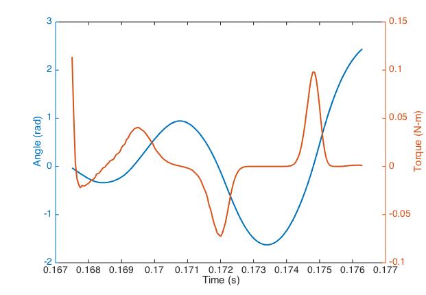
Here's what the angle and torque command during swing up look like, before it kicks into the linear controller.  This is actual measured data:


Finally, there's a simple state machine which chooses the controller to use at any given time - swing up, swing down, or stabilize up.

Here's a video showing the different control states:


August 13, 2016

Desktop Inverted Pendulum, Part 1

This is a relatively quick little project, but one that's been on my mind for more than a year now, and finally got around to building.

Inverted pendulums can be a pretty cool testbed for controls stuff.  They're relatively simple, but very non-linear systems, and there are a lot of approaches to swinging up and stabilizing the pendulum.  The Furuta pendulum style of machine is particularly interesting, I think.  If built right, they can be very small but have unlimited travel, unlike the car-pole style of inverted pendulum, which eventually runs out of track for the cart.  Although the full non-linear equations of motion are much more gnarly, for small motions the behavior is largely the same, so it's not actually any harder to stabilize.  

This post will cover all the mechanical stuff, and the next one will go through the controls I've done.  

Here's a video of it running, so you don't have to scroll through the whole post to find the only part you actually care about:


Like all good projects, this one starts with a motor.  A familiar motor.  I re-used the Turnigy 5208 gimbal motor I characterized a while back.  I spent a while thinking about what kind of motor I wanted to use for this project - I wanted low friction, no backlash (direct drive), and low torque ripple, to make control as pleasant as possible.  A direct-drive brushed servodisc would have worked great, except that I really wanted a motor with a hole through the center of the shaft.  This way I could pass the wires to the pendulum encoder through a slip ring, and get infinite rotation out of the top half of the pendulum.  Since I already had this gimbal motor on hand, I made some serious modifications to it to give it a hollow shaft and to kill its cogging torque.


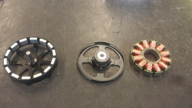
First step was pull off al the windings.  It needed rewinding anyway, since it was wound much colder than I wanted for 12V operation.  Then I split the laminations apart with a razor blade, re-flattened them in a vice, and glued them back together with a skew.  Skewing the stator like this almost completely kills the cogging torque (the closer you get to a full pitch of skew, the lower the cogging), at the cost of lowering your motor constant.


Here it is rewound, with 20 turns/tooth of 4 parallel strands of 22 AWG wire.  Stock the motor had 150 turns/tooth.


Machined a new housing for the stator, with extra-large thin section rotor bearings to fit a hollow shaft with a 12mm bore.


I forgot to take pictures of the rotor, but I basically just machined a new aluminum can, pressed the original rotor into it, and then machined away everything but the magnets and can from the original motor.  Here's the basic motor + encoder assembly.  The optical encoder was the only one I could find with a large enough disc to fit the  hollow shaft, so it defined the shape of the pendulum assembly.  I still had to machine a new hub for the disc though.


Motor cross section (minus windings and magnet, showing how the shaft and bearings work out:


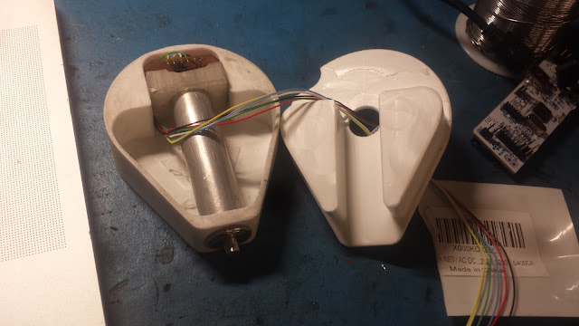
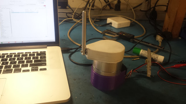
Here's the pendulum assembly that sits on top of the rotor.  The pendulum attaches to a spindle with a magnet stuck to the opposite end of the shaft.  An Allegro A1335 chip on a CNC-routed pcb outputs the angle of the magnet over SPI, which is passed through a slip ring back to the motor controller.


A big optical encoder is mounted to the bottom of the the motor, and is used for both motor commutation and pendulum control.  One of my little motor drivers mounts to the encoder housing.  I had to jumper an extra header to it to wire in power for the encoder.


Here's the unfinished version, with the pendulum stabilized.  I didn't have all the right pieces of plastic on hand to machine the housings from, so I started work on the control stuff with some 3D-printed housings to keep everything together.


I machined plastic housings out of some chunks of delrin, and turned a circular aluminum base.  Here's my favourite technique for making big circular plates:  Bandsaw out the rough shape, drill a hole through the center, use a big bolt as an arbor, and turn it round on a lathe:


Pretty pictures:


Lemo power connector goodness:


Stabilized upright: