March 29, 2013

PocketBoard v2: Metal Edition

Unfortunately, PocketBoard's pretty oak deck did not last for very long.  Repeatedly getting wet and drying out expanded some cracks already present in the wood, and eventually the deck split down its entire length.  Because the board was so useful (it noticeably increased my free-food acquisition rate), I quickly made a new deck out of the most readily available material:  carbon fiber aluminum.

The top of the deck was cut out of the side panel of an old PowerMac G5 case on a bandsaw.  Originally, I planned to have the Apple logo on the top of the deck, but Julian pointed out that the disassembly guide on the opposite side of the panel was much more interesting.


The 1/8" thick deck proved to be too flexible to use on its own, so I made an under-frame out of some 1/4" plate.  The outside profile was cut again on the bandsaw, while the cutout in the middle was made by hand interpolating (think etch-a-sketch) the curves on a manual mill and filing them smooth.


March 28, 2013

Another Differential

Back when I built the nifty spur gear differential for my electric tricycle, I chose to buy, well, spur gears rather than bevel gears like differentials traditionally use.  I did this partly because McMaster's spur gears are much cheaper than their bevel gears, and partly because I had the great LOLriokartdiff off which I could base my design.

A couple weeks ago, while reading through a build thread on RoboWars Australia I found pictures of some bevel gear sets originally intended for angle grinders, which were purchased from Ebay.  A quick search revealed that a number of Amazon retailers stock similar gears.  I ended up getting two sets of these, so I could find out how useful they were.

A few days ago, these came in the mail:


First impression:  They are very small.  The big one is ~1.8" diameter.  I didn't measure the pitch, but it looks pretty similar to the 20 pitch spur gears I used in the trike differential.  They're almost certainly sintered, so don't know if I'd trust them to withstand a melonpower.


In a differential, they would be assembled roughly like this:


I spent the better part of night morning machining the housing for the differential.  Because of laziness and oh god randomly sized helical bevel gears, I decided to not bother trying to CAD anything.  I basically just found some chunks of aluminum and winged it.

For output shafts I used some 1/2" keywayed shaft left over from my original differential.  Since the gears were bored out to 11mm, I turned a shoulder into the shafts.


The gears have some ground down keyway stock stopping them from rotating independently of the shaft, and a big countersunk bolt stops them from moving axially.


To make the housing, I started with some absurdly large timing belt pulleys that were basically solid aluminum round about 3.4-4" thick by 3" long.  The housing is composed of two parts, that are identical except for the six holes.  One side has clearance holes for 8-32 screws, while the other side is tapped.  The cylindrical grooves in each half retain a 8 mm shaft that goes all the way through, and holds the smaller gears.  I made the grooves by bolting the housing together with some paper shims separating the halves, and then drilling holes sized exactly for the shaft.  When the shims are removed, the shaft gets squeezed between the two halves, since the groove profiles are not quite full semicircles.


All the parts of the differential laid out:


All together.  To drive it, you would just bolt a sprocket or pulley through the same six bolts that hold everything together.


I sealed it up with a bunch of grease on on the gears.  And you know what?  Despite my lack of planning, it works beautifully.  Sure, there is a little bit of axial play in the output since I bored out the housing to the wrong depth, but that can be fixed with a washer or two.  Also, the steel-on-steel interface between the shaft and two small gears is definitely questionable.  The motion is significantly smoother than the spur gear differential, and there is absolutely no binding.  It is also a bit more radially symmetric than the spur gear differential, so it should work better at high RPMs, since it won't shake everything apart.  Which may be very important, depending on which of the few ideas I have for this I end up going with.

March 25, 2013

It Almost Looks Like A Bicycle

I made the seatstays using pretty much the same process as I did for the chainstays, but with carbon fiber cloth instead of bundles of tow.  I plan on adding an aluminum insert for the rear brake to clamp into.


 Rather than using a bunch of layers of cloth, I decided to try embedding some thin pre-made carbon fiber tubes into the seatstays, and only using two layers of cloth:


With the frame tacked together, I started making the lugs to reinforce the joints.  I found that the only way I could get a decent seal in the vacuum bag was to enclose the entire frame.  If I tried to pull a vacuum locally, the leak rate was too high to properly compress the joint.


This is what the reinforced head tube joint looks like after some sanding:


I did some work around the dropouts as well:


In an effort to make my vacuum bagging technique slightly more legitimate, I used peel ply and some resin-absorbing cloth around the seat cluster.  Unfortunately, this joint had pretty severe seams around the edges, but I don't know whether they are due to the the cloth or the mediocre vacuum I was able to get.


This being a zero-dollar project, I was concerned about how I was going to get a carbon fiber fork.  Molding one myself would have been very difficult, as the fork needs to interface with bearings and a stem, meaning it has to be more precise than I could manage with a foam mold.  My leading idea was to find a large plastic billet, CNC out a female two-part mold for the fork at Edgerton, and positive pressure molding it, like how real bike parts are made.

Out of curiosity, I sent out a query to reuse-ask, to see if anyone on campus had a working or only slightly broken carbon fiber fork they would be willing to part with.  I thought it was a bit of a stretch, but I got a response within four hours, from someone with a fork that had been crashed.


I sanded the area down to get a better picture of the damage.  With the paint removed, it actually didn't look quite as bad.  I sanded out all the cracks, which did not actually go all the way through the tube.


I applied a four-layer patch to the damaged area, starting with a small patch right over it.  Each additional layer was larger than the previous one, so that the patch gradually increased in thickness from the undamaged to damaged area.


I sanded down the patch, and stripped the rest of the paint off the fork.  I still haven't decided how to finish the surface yet.


With any luck, the frame should be finished within the week.  In terms of components, I have everything except for a chainring, a front tire, a headset, and a stem, so I should be able to build up the bike shortly after finishing it.

March 4, 2013

Tricycle Shenanigans, Pre-CPW Stress Testing

The tricycle has actually been done for a few weeks now.  The two things stopping me from doing a final writeup are that I have still not gotten around to taking nice pictures of it, and until yesterday, I did have any good videos either.  In the acquisition of the video, some parts of the trike were broken, so now the pictures have to wait until everything is fixed and pretty again.  Here is as close to a final picture as I have right now:


Before doing any thorough testing, I remade the stem, which I broke just before TechFair.  The original stem was made from a block of aluminum that was a little bit too small.  I had to use thinner bolts than I would have liked to, and they were the super-shady kind of bolt MITERS probably purchased by clicking "sort by lowest price."  The fit around the handlebars was never ideal, so I had to crank the bolts especially tight to stop the bars from rotating.  I overtightened one of the shady bolts, and sheared it off inside the stem.  I may have been able to remove the left over bolt-stump, but the failure was a good excuse to make a new and better stem.

Here's the back end of the old stem, with embedded bolt:


I made the new one much better looking.  I started out by facing all six sides of a large chunk of aluminum, which used to be part of an even larger billet that found its way to MITERS from the CSAIL stock room.


To make the circular lip that holds down the headset bearings, I clamped the block to an indexing table:


Also using the indexing table, I milled a nice curved face into the front of the stem, à la Amy:


I drilled and countersunk all the holes on the mill, and cut the slots on the bandsaw.  All the corners were rounded on a belt sander, and then finished with some sandpaper by hand.  Also, this time around the headeset cap sits flush with the surface of the stem rather than sticking above everything.


And finally, here is some real footage of the trike in action!


Jaguar and I started out by taking it to the Kresge oval, but the path turned out to be too rough in places to sustain very high speeds.  On the way there from EC, we attempted some 2 person riding, to determine whether it would be possible to trike around with  prefrosh on the back during CPW.  This kind of worked.  The second person rides by standing on the back platform and leaning forward, holding onto the driver's shoulders.  This riding method caused two problems - one per foot.  If the rider's feet are hanging off the back of the platform, and they lean back, their heels put pressure on the things sticking out behind the metal:  The battery cover on the left, and the power switch on the right.  The acrylic battery case snapped into 3 pieces, and the power switch also broke.  I was able to duct-tape the switch together enough to keep it working, but it will need to be replaced.  I will probably remake the battery cover out of carbon fiber, since carbon fiber seems to be my answer to everything right now.  On the way back to EC via the Infinite Basement Corridor, we realized it was two thirty in the morning and no one would know/care if we rode around in the basement tunnels.  Due to their width and slippery floors, the tunnels around Stata are especially good for drifting.  This lead us to what may be the best (well, very early on Sunday mornings, at least) small electric vehicle racing grounds on campus:  the parking lot under the Stata Center.  The concrete surface makes for excellent traction.  It has regular pillars which would make setting up a race course easy, but it also has long straights all the way across its length and width.  There isn't enough space to max out the trike, but we easily got it into the upper 20's (estimate based on which gears we were in) on the straights.

Here it is in its ugly but still functioning state, pre Stata:


The night morning of riding ended when I accidentally pulled loose one of the leads to the hall effect sensor board loose while fiddling with the power switch.  

Some thoughts and observations:

-Some serious prefrosh-proofing would be required to make this a CPW event (e.g. no more acrylic or switches sticking out)
-Swappable battery packs are awesome.
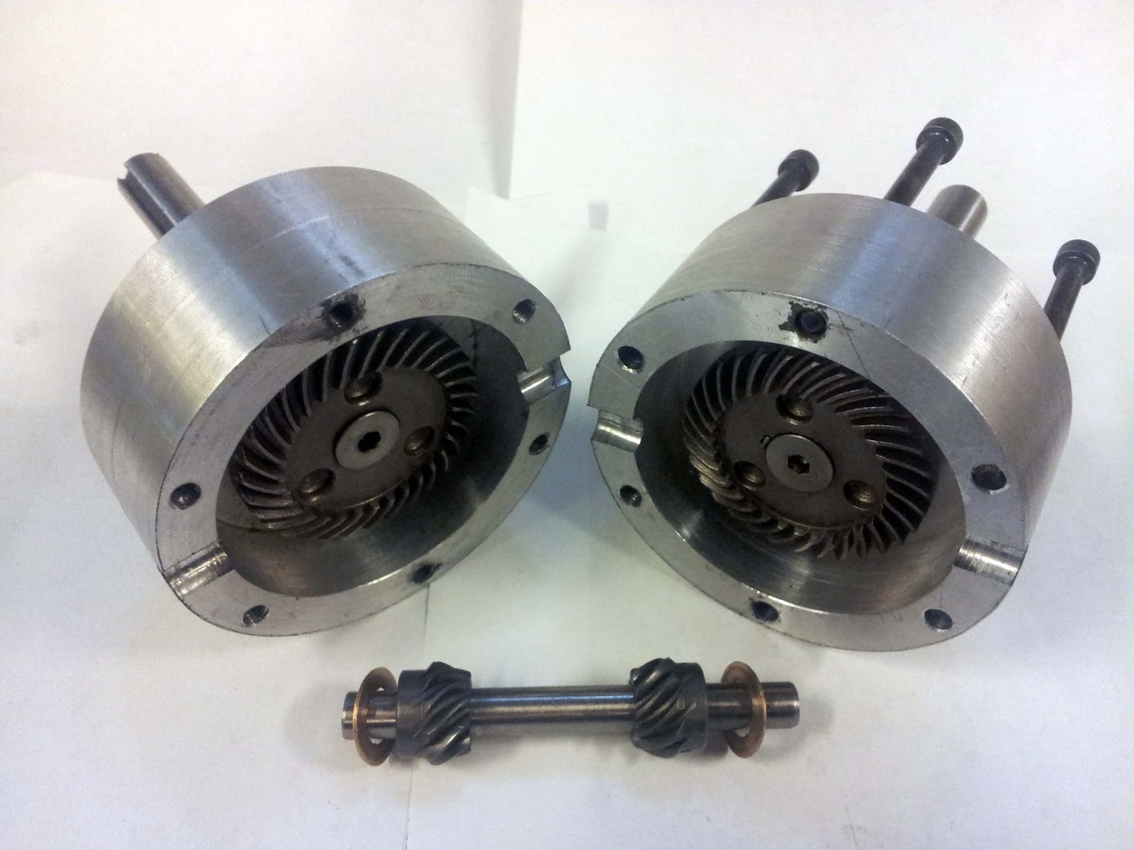
-Even with the current limiting set to around 80% of maximum on the motor side, the controller still sometimes cuts out, especially if you gun the throttle right after shifting.  According to Shane, getting a Kelly with the high speed option would probably eliminate this problem.  To be fair, this is an awfully big motor to be driving with this controller
-MITERS Small EV Rallies in the Stata Garage need to become a thing.  All the pillars and other obstacles would make it pretty easy to set up a temporary racetrack.

Playing with Real Carbon Fiber™

Last semester, the class How To Make (almost) Anything (MAS.863) took place two floors above MITERS, so when their leftover materials were cleared out, MITERS members collected some of them.  These materials included a proper vacuum bagging pump that can be run continuously, as well as some real woven carbon fiber cloth.  


I made a male foam mold for the seatstays, and vacuum bagged it with wetted-out carbon fiber cloth.


Here's the part during the curing process:


And here it is out of the bag, after one layer of carbon.  Unfortunately, the bag did not conform to the shape fo the tubes as much as I had hoped, so there were a bunch of wrinkles in the part.  Also, in the places where the two sides of the bag meet around the edge of the part, the vacuum pulled some fabric into the seam and away from the mold:


When I sanded down the seams, I found that there were gaps under them:


In places where the bag didn't wrinkle, the surface finish was really nice:


Despite the defects in the part, I decided to go ahead and add more layers of carbon fiber.  There were fewer wrinkles the second time around, but there were still long voids along the seams.  Also, I really overbuilt this part.  The tubes are much wider diameter and much thicker than they need to be.  I plan on remaking this part with a somewhat different technique, to make it lighter and less bulky.


When I made the chainstays, I did not leave enough clearance for a tire.  I cut out a profile to make room for the tire, and then covered the gaps in the tubes with two layers or carbon fiber cloth:


Finally, I inserted a carbon fiber shim to bring the I.D of the seat tube down to the appropriate diameter for clamping a seatpost.  The shim was yet another piece of the oar, that just happened to be the exact dimensions I needed: